Avionics and aerospace sensor windows and optical components face thermal shock, outgassing limits and vibration qualification that terrestrial parts never see, so the cold-processing steps that hold figure and edge integrity under those loads are where most field failures actually start. This note walks through the failure modes that show up, how to measure them, and the design rules that keep them off the first article.
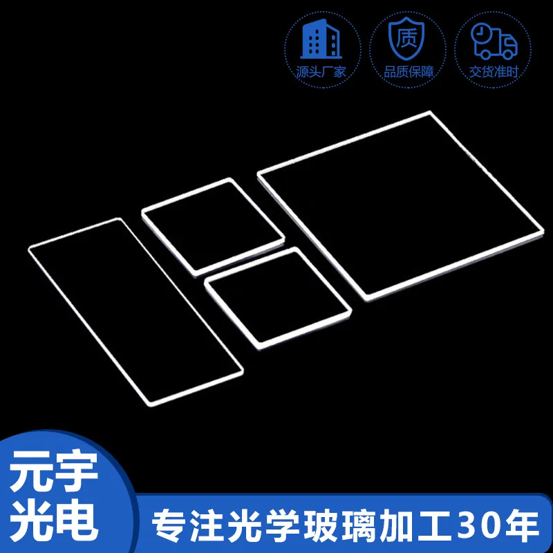
Optical Glass Cold Processing in Aerospace and Avionics Optics
Cold processing covers grinding, polishing, edging, drilling and figuring of optical glass without changing its bulk chemistry, and for aerospace it has to deliver a part that survives the platform's environment rather than just a clean optical surface. A window on a sensor pod may see a wide thermal swing, sustained vibration and a hard vacuum or low-pressure environment, so the way the edge is finished and the way residual stress is managed matters as much as the transmitted wavefront. The part is usually built to a flight-qualification file rather than a generic optical drawing.
Common failure modes and how they show up
The failure modes that actually reach the field are edge chipping on thin or large parts under vibration, subsurface damage that lowers strength, figure or wedge drift after mounting, coating adhesion loss after thermal cycling, and particulate left by poor cleaning. Chips tend to appear at the chamfer where a clamp loads the edge, and a small chip can propagate into a crack under sustained vibration. Subsurface damage from aggressive grinding is invisible to a surface scan but reduces the proof strength of the part.
Inspection and measurement
Figure is checked by interferometry, surface quality by the scratch-dig scale, and edge and chamfer by optical or tactile inspection against the edge-chip limit. Wedge or parallelism is measured by autocollimation or a comparable method, geometry by a coordinate measuring machine, and stress birefringence where mounting induces it. The point is to measure the parameters that the environment will exercise, not only the ones that are easy to scan.
Coating and deposition considerations
Coatings for avionics need dense, adherent stacks built to survive thermal cycling and, where relevant, a hard top layer against cleaning and abrasion. Adhesion is qualified across the temperature range rather than at room temperature alone, and outgassing is controlled by limiting organic content in the stack. State which face carries the functional layer on the drawing, because a coating on the wrong face is a common, avoidable rejection at first article.
Design rules that reduce cost
Cost comes down by minimising custom geometry, standardising on available blanks, relaxing tolerances wherever function allows, and choosing a substrate that is already in stock. Designing the part for fixture-friendly clamping avoids the edge stress that causes chipping, and keeping the figure callout to what the optical function needs prevents an expensive polish that the system cannot use. A part that drops into an existing holder is cheaper and lead-time safer than a bespoke one.
How it compares with the alternatives
Against moulded glass or glass-ceramic, cold-processed optical glass is flexible and cost-effective at moderate volumes but needs more handling per part. Against sapphire, glass is far cheaper and easier to figure but softer and more thermal-expansive. The trade is between lead time, qualification effort and unit cost: cold processing wins where volumes do not justify a mould and where a flight-qualified glass is already approved on the platform.
Requirements specific to Aerospace and Avionics Optics
Aerospace and avionics add a wide thermal range, vibration and shock qualification, and outgassing limits to the usual optical requirements. Specify edge integrity and subsurface-damage control for vibration, hold figure and wedge across the thermal range, and qualify coating adhesion and outgassing. Choose a substrate with flight history or run qualification, and keep full batch traceability with a first-article inspection so a replacement part reproduces the original.
- Edge integrity and subsurface-damage control for vibration
- Figure and wedge held across the thermal range
- Coating adhesion and outgassing qualified
- Full batch traceability and first-article inspection
Framework references: ISO 10110 for surface figure, surface quality and edge-chip limits (e.g. ISO 10110-14). Outgassing and total mass loss should be stated against the relevant aerospace or space materials specification for the current issue, and vibration or shock against the platform's environmental file.
Selection data at a glance
| Parameter | Typical capability | Notes |
|---|---|---|
| Edge chip | Per ISO 10110-14 | Vibration risk |
| Surface quality | Scratch/dig per ISO 10110-7 | Typical 60-40 |
| Figure | PV ≤ 0.5 µm standard | Across temperature |
| Wedge | 2 arcmin achievable | Beam stability |
| Outgassing | Low total mass loss | Flight class |
| Traceability | Batch plus FAI | Reproducible |
Frequently asked questions
Why does edge chipping matter in avionics?
Sustained vibration can propagate a chip into a crack. Controlling the edge and chamfer per ISO 10110-14 is the practical mitigation, and it is cheaper than designing around a thicker part.
Does thermal cycling affect the figure?
Differential expansion between the window and its carrier can, so specify a low-expansion substrate or a compliant mount, then let wedge and surface-form tolerances define how much of that drift reaches the image.
Are standard optical glasses flight-qualified?
Not automatically. It depends on the platform; choose a substrate with qualification data or run the qualification the file requires before series release.
Need a quotation for optical glass cold processing?
Send your drawing, target specification or coating requirement and an optical engineer will reply within 24 hours with a price and a lead time.
Request a Quote Email an engineer