Specifying IR filters for IPL and beauty devices is largely a matter of deciding which three numbers actually govern the application and letting the rest follow. This guide walks through the parameters that belong on the drawing, the tolerances that genuinely change the price, and the specification items that are routinely left out and then argued about at first article.
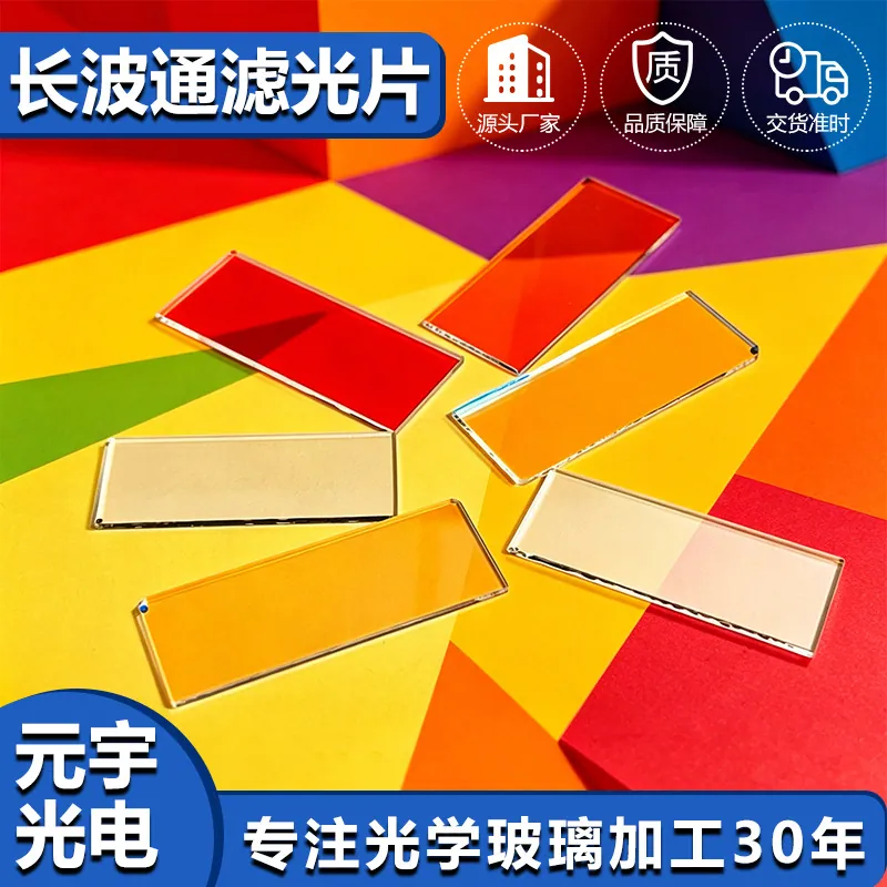
IR Filters in IPL and Beauty Devices
In IPL and beauty devices, that translates into a specific set of requirements rather than a general preference for quality. Light-based beauty devices push high pulsed energy through a small filter, often at close range to skin. The filter has to define the treatment band precisely, block the wavelengths that would burn rather than treat, survive thousands of flashes without drifting, and stay cool enough not to injure the user. Cost matters too, because these are consumer products made in volume.
The tolerances that actually matter
An IR filter is specified by its curve, so the tolerances that matter are spectral. A typical commercial part holds the cut-on wavelength to plus or minus five nanometers and the visible transmission to within a few percent of nominal; precision imaging parts tighten the wavelength to two nanometers and also constrain the slope of the transition. All of these numbers are only meaningful at a stated angle of incidence, and the acceptance angle belongs on the drawing next to the spectral tolerance. Mechanical tolerances follow the mounting: thickness to plus or minus 0.02 mm for a drop-in window, outline to plus or minus 0.05 mm, and a chamfer on every edge. In IPL and Beauty Devices, the specification most often forgotten is the permitted variation of color across the aperture, which is what a user actually notices when a wide lens produces a green frame edge.
Design rules that reduce cost
The design decisions that matter are the cut-on wavelength, the acceptance angle and the mounting. Place the cut-on where the sensor's quantum efficiency falls and its NIR sensitivity rises - most silicon sensors need the edge between 650 and 680 nm - and then decide how much of the aperture range must hold color accuracy. If the lens is fast or wide, either accept a wider transition or add an absorptive element. Leave a clear margin of at least 0.5 mm for mounting and a chamfer on both edges. Where the filter sits behind the lens rather than in front of it, remember that the ray bundle is no longer telecentric: the effective angle can exceed thirty degrees even in a modest system, which is exactly where a dichroic design begins to lose color fidelity in IPL and Beauty Devices.
Coating and deposition considerations
Dichroic IR-cut designs run from roughly twenty to sixty layers of alternating high- and low-index oxides, with the layer thicknesses controlling both the position and the steepness of the edge. Ion-assisted deposition is the standard process because it produces dense layers that do not shift with humidity - an unassisted coating can move several nanometers after a week in a humid room. The residual reflection in the visible band has to be managed, since a strong reflection produces the green or magenta glint familiar on poorly coated camera windows; broadband AR layers are usually added on top of the dichroic stack to suppress it. For IPL and Beauty Devices, also decide whether a hard, hydrophobic outer layer is required, because it changes both the durability and the price of the part.
How IR filters works in practice
An IR filter removes a spectral band the sensor would otherwise record, and it does so in one of two ways. A dichroic filter reflects near-infrared light with a multilayer interference stack, so nothing is absorbed and the part stays cool; a blue or absorptive glass filter removes the same band by absorbing it in the bulk material. Dichroic designs give sharper edges, higher visible transmission and precisely tuneable cut-on wavelengths, but the edge moves with angle. Absorptive glass is angle-insensitive and cheap, but it is thicker, heavier and its cut-on is fixed by chemistry. In IPL and Beauty Devices, the choice usually comes down to how much of the field of view arrives off-axis: a narrow acceptance cone favors a dichroic design, while a wide-angle lens often needs an absorptive or a hybrid solution to avoid color shading across the frame.
Requirements specific to IPL and Beauty Devices
In IPL and beauty devices, that translates into a specific set of requirements rather than a general preference for quality. Light-based beauty devices push high pulsed energy through a small filter, often at close range to skin. The filter has to define the treatment band precisely, block the wavelengths that would burn rather than treat, survive thousands of flashes without drifting, and stay cool enough not to injure the user. Cost matters too, because these are consumer products made in volume.
- Cut-on between 470 and 650 nm depending on treatment
- Flash-to-flash stability over the device lifetime
- High flux tolerance with thermal shock resistance
- Cosmetic-grade finish on the user-facing surface
IEC 60335 and IEC 62471 photobiological safety context for the finished device, plus RoHS and REACH declarations for the component.
Selection data at a glance
| Parameter | Typical value | Notes |
|---|---|---|
| IR-cut cut-on | 630-700 nm | Tuned to the sensor response |
| Visible transmission | T ≥ 90 %, R ≤ 1 % | Average 420-620 nm |
| NIR blocking | OD2 - OD4 (1 % - 0.01 %) | 700-1100 nm |
| Edge steepness | 10-30 nm transition | Dichroic designs |
| Angle of incidence | 0-30 deg specified | Passband shifts blue with angle |
| Wavelength tolerance | ± 5 nm standard, ± 2 nm precision | Measured at stated AOI |
| Substrate | B270, D263T, blue glass, sapphire | Absorptive option removes NIR without angle shift |
| Thickness | 0.3-3 mm | 0.55 - 1.1 mm typical for camera windows |
| Environmental | Humidity, salt spray, abrasion tested | MIL-C-48497 / MIL-PRF-13830B |
Frequently asked questions
How tight can the wavelength tolerance be?
Plus or minus five nanometers is routine and plus or minus two nanometers is achievable on precision imaging parts. Tighter than that usually requires sorting parts by measurement, which raises cost sharply.
What cut-on wavelength should I specify?
Most silicon sensors need the cut-on between 650 and 680 nm, before the sensor's NIR response climbs. If the application also has an 850 nm illuminator nearby, tighten the blocking to OD3 and confirm the edge position against the source wavelength.
Why does my image look green at the corners?
That is angular shift. The dichroic edge moves toward shorter wavelengths as the angle of incidence increases, so off-axis rays lose blue light and the frame edges shift color. Solutions are a wider transition, an absorptive element, or moving the filter closer to the stop.
Need a quotation for ir filters?
Send your drawing, target specification or coating requirement and an optical engineer will reply within 24 hours with a price and a lead time.
Request a Quote Email an engineer