There is always more than one way to build a hyperspectral imager, and the options are not equally good at everything. A filter wheel, a linear variable filter, a mosaic filter array and a dispersive spectrometer all deliver spectral data, but they differ by an order of magnitude in cost, volume and how much light they waste. This article compares IR filters against the alternatives, using the criteria that decide a real instrument: spectral resolution, throughput, calibration stability and the cost of the first article.
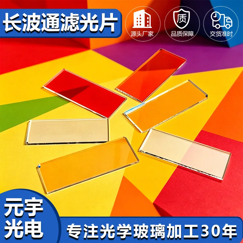
IR Filters in Hyperspectral Imaging
In hyperspectral imaging, that translates into a specific set of requirements rather than a general preference for quality. The instrument has to separate a scene into narrow spectral bands, and it has to do so with enough signal that the measurement is limited by the detector rather than by the optics. An IR bandpass filter placed in front of a sensor achieves this by transmitting one band and rejecting everything else, which means the rejected light is simply lost. That is an acceptable trade in the shortwave infrared, where illumination is usually controlled and the scene is not photon-starved, and it is a poor trade in passive remote sensing where every photon counts. The comparison that matters is therefore not which filter is best in isolation, but which spectral architecture suits the light budget of the application.
Substrate and material selection
The substrate decides the usable band and the thermal behaviour of the coating. Shortwave infrared filters, roughly 900 to 1700 nm, are usually deposited on fused silica or B270 because both transmit well and are dimensionally stable. Filters that must reach beyond 2500 nm need calcium fluoride, sapphire or silicon, and each brings a different refractive index, a different coefficient of expansion and a different cost. Silicon is cheap and transmits deeply into the infrared, but it also has a high index, which increases reflection loss and makes broadband anti-reflective design harder. For mosaic arrays where hundreds of filter elements sit side by side on one wafer, the substrate has to be selected for coating uniformity across the full aperture, because a thickness error at the edge of the wafer shifts every band that sits there.
What drives cost and lead time
Cost in hyperspectral optics is driven by the number of distinct coating runs rather than by the area of glass. A single bandpass filter is a routine part; a mosaic array with sixty-four different bands requires sixty-four deposition steps, sixty-four sets of process controls and a photolithographic patterning sequence between them, and each step multiplies the yield risk. A linear variable filter avoids the patterning but demands a controlled thickness gradient across the substrate, which is a deposition challenge rather than a patterning one and is priced accordingly. The second driver is centring tolerance: a band that has to be centred within one nanometre costs substantially more than the same band specified to ten nanometres, because the former requires in-situ optical monitoring rather than a timed deposition.
The tolerances that actually matter
Spectral specifications are what separate a working instrument from a calibration problem. The useful numbers are the centre wavelength and its tolerance, the full width at half maximum, the peak transmission, and the out-of-band blocking expressed as an optical density over a stated range. Blocking is routinely under-specified: a filter quoted as OD4 may only reach OD4 in the visible and fall to OD2 in the near infrared, which is exactly where the stray light is coming from. Temperature shift matters as well, because a coating centred at 1550 nm moves with temperature, and an instrument that operates outdoors will see a band drift that the laboratory specification never mentions. Where the filter is used with a broadband source, the integrated transmission across the band matters more than the peak value.
How it compares with the alternatives
A filter wheel is the cheapest way to get a small number of bands and the slowest way to acquire a cube, because the wheel has to move between exposures. A linear variable filter gives continuous spectral coverage in a pushbroom geometry, with the trade that the spectral axis is tied to the spatial axis, so a moving scene smears the spectrum. A mosaic filter array captures a full cube in a single exposure, which is the right answer for dynamic scenes and the wrong answer for high spectral resolution, because each band receives a fraction of the available light. A dispersive spectrometer offers the highest resolution and the best throughput, at the cost of a slit, an alignment budget and a much larger instrument. IR bandpass filters win wherever the band count is modest, the illumination is controlled and the instrument has to be small, rugged and cheap.
Requirements specific to Hyperspectral Imaging
Hyperspectral instruments add constraints that ordinary filter specifications do not capture. The scene is often illuminated rather than self-luminous, so throughput converts directly into exposure time and into motion blur in a moving platform. Calibration stability over the life of the instrument matters more than absolute accuracy, because the data product is a comparison between bands rather than an absolute radiance. Out-of-band blocking is therefore a system requirement rather than a filter detail, and it should be specified over the detector's full sensitivity range. Where the instrument is field-deployed, temperature shift and humidity resistance belong on the drawing alongside the spectral numbers.
- Centre wavelength, FWHM and peak transmission stated with tolerances
- Out-of-band blocking specified over the detector's full range, not just the visible
- Temperature shift of the band quoted for field-deployed instruments
- Band count drives cost more than aperture does
ISO 10110 drawings for the substrate, and spectral measurements traceable to a calibrated spectrophotometer over the full operating band.
Selection data at a glance
| Parameter | Typical value | Notes |
|---|---|---|
| Band options | 900-1700 nm SWIR, 400-1000 nm, custom | Narrowband or broadband |
| FWHM | 10-50 nm standard, 3 nm achievable | Narrower costs more |
| Centre wavelength tolerance | ± 5 nm standard, ± 1 nm on request | In-situ monitoring |
| Peak transmission | over 90 % in band, over 95 % achievable | Per surface |
| Blocking | OD4 average, OD3 minimum in band | State the range |
| Substrate | B270, fused silica, sapphire, silicon, CaF2 | Band dependent |
| Temperature shift | under 0.03 nm/K typical | Thin-film dependent |
| Surface quality | 40-20 scratch-dig standard | 60-40 for imaging |
| Size | 3-100 mm square or round, custom shapes | Mosaic arrays on wafer |
Frequently asked questions
How many bands can a mosaic filter array realistically carry?
Practical arrays run from sixteen to sixty-four bands, limited less by patterning than by yield. Every additional band means another deposition and lithography step, and the yield of the full sequence is the product of the individual yields. Beyond about sixty-four bands the array becomes difficult to build economically and the per-band signal becomes the limiting factor.
Why does out-of-band blocking matter so much?
Because under-specified blocking is a signal-to-noise problem rather than a cosmetic one. If the filter transmits a small fraction of light outside the band, and the scene is bright at those wavelengths, the stray light adds directly to the measurement and cannot be separated afterwards. The blocking specification should therefore cover the entire range where the detector is sensitive.
Can one filter serve several instruments?
Often yes, if the band specification is written around the physics rather than around a particular detector. Filters are more reusable than arrays, because they are discrete parts with no patterning and no wafer-level alignment. Standardising the band set across a product family reduces the number of coating runs and the number of spare parts.
Need a quotation for ir filters?
Send your drawing, target specification or coating requirement and an optical engineer will reply within 24 hours with a price and a lead time.
Request a Quote Email an engineer