Cover glass and display panel manufacturing starts with a large thin sheet that has to become a rectangle, a circle or a freeform outline with an edge the rest of the process can live with. That last clause is where most laser cutting programmes go wrong: the cut itself looks fine, and the edge chips, taper or micro-cracks only show up three steps later at polishing, printing or bonding. This guide sets out what to specify on the cut so that the downstream process is not designing around the edge it was given.
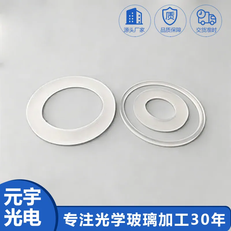
Laser Cutting of Glass in Display Panel and Cover Glass
Laser cutting of glass is a non-contact, process-controlled way to separate a sheet along a defined path, using a focused high-power beam that vaporises a very narrow kerf rather than mechanically scoring and breaking the material. In display and cover glass production it appears at two points. The first is blanking, where a large sheet is cut into individual lens or cover outlines before any edge refinement, coating or bonding, and the cut is the only edge the part will have for a while. The second is outline cutting on toughened or laminated stacks, where the material has changed and the beam energy has to be re-tuned. Panel glass adds two constraints that ordinary glass does not: the sheets are very thin relative to their size, so heat handling and fixture stability dominate, and the material is frequently chemically strengthened, which changes its reaction to a local thermal event entirely.
How laser cutting of glass works in practice
The process is governed by how quickly energy is delivered and removed. A focused beam deposits energy into a small volume, the glass reaches its decomposition temperature in that volume, and the vapour expands out of the kerf. Everything about edge quality follows from that. Too little energy and the full thickness is not removed cleanly, leaving a recast layer and an irregular exit edge; too much and the vapour is violent enough to throw droplets onto the sheet and to open micro-cracks back from the cut. Moving the beam at the wrong speed produces a tapered kerf, which becomes a wedge in the finished part. On thin, wide sheets the same settings behave differently at the centre and at the edge of the sheet because the heat path changes, which is why a cut that passed on a small coupon can fail on production geometry. A filleted or scalloped path is used on display outlines because it distributes the energy over the corner rather than concentrating it.
The tolerances that actually matter
Four tolerances decide whether the downstream process is happy. Cut dimension, which for a blank that will be ground and polished on all edges is often allowed more than a buyer expects, but for a part that goes straight to bonding is tight because it becomes the assembly gap. Edge chipping at the exit side, which is the dominant quality metric on thin sheet and the one that determines yield. Kerf width and taper, since a tapered kerf means the two faces are not parallel, which is wedge once the part is assembled into a stack or a bonded optical assembly. And heat-affected zone depth, the micro-crack and recast layer just inside the cut, which is the item that shows up as a crack weeks later rather than at the outgoing inspection. Surface quality on the cut face is usually outside the optical specification because the face is subsequently ground or fire-polished, but on a part that keeps the laser edge it becomes the limiting optical feature and has to be specified. In practice, the useful set is dimension, chip limit, taper and a stated requirement for the recast layer to be removed.
Design rules that reduce cost
Most of the cost on this application is rework caused by geometry rather than by the cut. Keep the design within the machine's usable field and away from fixture rails, because a part that overhangs the fixture is a part whose heat path changes halfway through the path. Avoid acute internal corners; a small radius at an inside corner costs nothing and removes the highest-chipping geometry on the part. Where the outline allows, a lead-in and lead-out that starts on a straight edge and ends on a straight edge measurably improves exit quality. Specify the finished part dimension rather than a nominal plus tolerance, and let the cutting allowance be the supplier's problem rather than the customer's, which is what makes the supplier able to hold yield. Where the part is thin and large, decide early whether it will be cut as a single sheet or as part of a panel with the surrounding material retained until later, because the fixture and support strategy differ and one of them is normally cheaper.
Coating and deposition considerations
Coating does not usually interact badly with laser cutting, but two things are worth settling. First, whether the cut happens before or after coating, since a coating applied first adds a layer whose edge behaviour the beam has to handle and which is then exposed along the cut line. Second, whether the panel is chemically strengthened before cutting, since strengthened glass has a much higher threshold for the same defect population and behaves differently under a rapid thermal event than annealed soda-lime. Where a hard or anti-reflective coating is applied afterwards, the cut edge itself is often left uncoated, and it is then the weakest surface in the part for handling, abrasion and moisture ingress. Where the blanking operation is followed by edge grinding and polishing, the practical requirement is that the recast layer be removed before polishing begins, since polishing into a recast layer pulls it out and produces a visible flat.
Handling, cleaning and packaging
Large thin cut parts are mechanically fragile in a specific way: they are strong in plane and weak out of plane, so a part held correctly is safe and a part held by an edge is not. Specify the handling method for the cut blanks, and specify a fixture rather than a stack for anything under about a millimetre, since a stack of thin blanks with air between them deforms under its own weight and the parts do not go back. Cutting debris and recast droplets are the other practical issue; a part that will go straight into polishing should arrive free of glass dust, and dust on the edge is what becomes a polishing inclusion and a visible flat. Packaging should be a rigid crate with individual support, and the incoming inspection should be on the edge rather than on the face, at a magnification that can actually see the chip limit being claimed.
Requirements specific to Display Panel and Cover Glass
Display panel and cover glass production blanks large thin sheets on a tight dimensional budget and then sends the cut edge through grinding, polishing, coating and bonding, so the cut has to be specified against the downstream process rather than on its own. State the finished part dimension, the edge chip limit, the permitted taper and the requirement to remove the recast layer before polishing, and set a kerf width appropriate to the downstream allowance. Keep the geometry within the machine's usable field, replace acute internal corners with radii, and use lead-in and lead-out on straight edges. Where the sheet is chemically strengthened, say so on the drawing so the process is set for it, and require delivery free of recast dust with individual support rather than stacking, since a flat that starts as a polishing inclusion is a flat nobody recovers.
- Finished part dimension, edge chip limit, taper allowance and recast removal all stated on the drawing
- Recast layer required to be removed before polishing begins to avoid pulled-out flats
- Kerf width set against the downstream grinding allowance rather than chosen for speed
- Geometry kept inside the machine field, acute internal corners replaced with radii
- Individual rigid packaging with no stacking of thin blanks to avoid out-of-plane deformation
Framework references: ISO 10110 for surface figure, surface quality and edge-chip limits on the finished part. Chemically strengthened glass and display panel products may be subject to additional supplier and industry specifications for edge strength, and any requirement should be taken from the current official text or the material supplier's datasheet in force at the time of ordering. Restricted-material declarations are the supplier's to state for the actual glass and any applied coating.
Selection data at a glance
| Parameter | Typical capability | Notes |
|---|---|---|
| Cut dimension | To finished part tolerance | Assembly gap |
| Edge chip | Stated chip limit on exit side | Primary yield metric |
| Kerf / taper | Match grinding allowance | Wedge when stacked |
| Recast layer | Remove before polishing | Prevents flat |
| Lead-in / lead-out | On straight edges | Exit quality |
| Packaging | Individual rigid support | No stacking |
Frequently asked questions
Why does the cut look fine but the polished edge show flats?
Usually because polishing began before the recast layer was fully removed. The recast and micro-crack zone left by the cut sits just inside the kerf, and polishing into it pulls material out rather than smoothing it. Requiring the recast layer to be removed before polishing is cheaper than recovering the parts afterwards.
Does chemically strengthened glass need different cut settings?
Yes. Strengthened glass has a very different response to a rapid local thermal event than annealed glass, and settings tuned for annealed soda-lime can produce micro-cracking that appears later. State the strengthening on the drawing so the process is set for the actual material.
How tight should the cut dimension be on a blank that will be ground?
Looser than instinct suggests. If every edge is subsequently ground and polished, the cutting allowance can absorb tolerance and the cost falls. Tight tolerance is justified when the part goes straight to bonding or when it keeps its laser edge, and in that case the edge itself becomes the limiting optical feature.
Need a quotation for laser cutting of glass?
Send your drawing, target specification or coating requirement and an optical engineer will reply within 24 hours with a price and a lead time.
Request a Quote Email an engineer