Specifying AR coated glass for an automotive head-up display is largely a matter of deciding which three numbers actually govern the image the driver sees, and letting the rest follow. This guide walks through the parameters that belong on the drawing, the tolerances that genuinely change the price, and the specification items that are routinely left out and then argued about at first article.
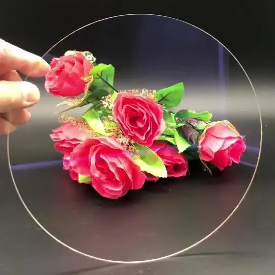
AR Anti-Reflective Glass in Automotive HUD
In automotive head-up displays, that translates into a specific set of requirements rather than a general preference for quality. A HUD projects a virtual image through a chain of mirrors and windows, so every uncoated surface returns a fraction of that light back into the optical path. In a windshield-projection HUD the ghost image is separated from the primary image by the windshield's own wedge angle; in an AR-HUD with a field of view of ten by four degrees and a virtual image distance beyond seven metres, the same four percent per surface is spread across a larger pupil and becomes visible as veiling glare and a second, dimmer image. Dust covers, fold mirrors and the combiner window are therefore specified photometrically, not only dimensionally.
The tolerances that actually matter
AR specifications are photometric rather than dimensional. The useful numbers are average reflectance across the display band, maximum reflectance at the worst wavelength, transmission, haze, and the residual colour of the reflected light. An automotive display emits in a narrower band than a laboratory instrument but at far higher luminance, typically 10,000 to 15,000 cd/m2 at the panel to deliver around 10,000 cd/m2 to the eye after the optical chain, so a coating tuned only to the visible average will still show a magenta or cyan cast at the edges of the image. On the mechanical side, the tolerances that move cost are surface form, meaning power and irregularity rather than flatness alone, wedge or parallelism on transmissive windows, and chamfer control on thin parts. A 0.5 mm window that has to hold two arcminutes of wedge is a different manufacturing problem from the same window at ten arcminutes.
Design rules that reduce cost
Deciding what to coat is as important as deciding how. Coat both faces of any window that sits in the optical path, because the second surface contributes as much reflected light as the first. Keep the design band as wide as the application genuinely allows: a 420-680 nm broadband stack costs less than a narrow notch that must be centred to a few nanometres. Avoid specifying a functional coating on a curved surface unless the curvature is required optically, since deposition uniformity across a curved fold mirror drives both tooling and yield. Where the part is a protective dust cover rather than an imaging element, an anti-glare etch is often sufficient and cheaper to qualify. Finally, fix the substrate early: ultra-clear float glass and B270 cost roughly the same, while fused quartz or sapphire multiply the material line and add finishing time.
Coating and deposition considerations
AR stacks are built from alternating low-index silica and higher-index oxides such as niobium, tantalum or titanium oxide, deposited in four, six or more layers to flatten the reflectance curve across the band. On automotive parts the stack must also survive the qualification regime: 85/85 humidity, salt spray, thermal cycling from -40 to +105 degrees C, and abrasion tests that a laboratory coating never sees. That pushes the design towards dense oxide layers and a hard top surface rather than the softer fluoropolymer finish used on consumer optics. Where the part is a combiner the requirement flips: a partial reflector needs a controlled, uniform reflectance rather than a minimum, and the tolerance applies to reflection rather than transmission. Specify which face carries the functional layer, and state it on the drawing, because reversing front and back is the most common first-article failure.
How AR coated glass works in practice
An anti-reflective coating reduces the light that bounces off a glass surface instead of passing through it. Uncoated optical glass reflects roughly four percent per surface, which means a window in a HUD path returns about eight percent of the display luminance as stray light. A single-layer coating can bring that to about one and a half percent, and a multi-layer stack to below half a percent average across the band. The same physics applies in reverse to a combiner, where the coating is designed to reflect a controlled fraction of the projected image towards the driver while transmitting the road scene behind it. In both cases the coating changes the photometry of the assembly rather than its geometry, which is why the numbers belong on the drawing next to the tolerances instead of in a separate coating note.
Requirements specific to Automotive HUD
Automotive qualification adds a regulatory and environmental layer that laboratory optics never carries. Displays must remain legible under the illumination conditions described in ISO 15008, and the optical assembly has to hold its image position across the full temperature range, which makes surface form stability and mounting geometry as important as the coating itself. Solar load is the other constraint: a HUD aperture can concentrate sunlight onto a fold mirror or onto the panel, and the resulting thermal gradient is a design driver rather than a test result. Parts are usually specified against IATF 16949 process controls and ECE R43 glazing requirements, with PPAP documentation on the first article.
- Photometric specification: average and worst-case reflectance across the display band
- Surface form and wedge tolerances that hold image position over temperature
- Automotive environmental qualification: 85/85 humidity, salt spray, -40 to +105 C
- Documented coating face and a PPAP-ready first article
ISO 15008 context for in-vehicle visual information, ISO 10110 drawings, ECE R43 glazing requirements and IATF 16949 process documentation.
Selection data at a glance
| Parameter | Typical value | Notes |
|---|---|---|
| Reflectance per surface | R ≤ 0.5 % average, R ≤ 0.2 % achievable | 420-680 nm |
| Transmission gain | up to 99 % single side, over 99 % both sides | Versus 92 % uncoated |
| Band options | 420-680, 430-700, 400-1100 nm | Matched to the display spectrum |
| Substrate | ultra-clear float, B270, borosilicate, quartz | 0.5-3 mm typical |
| Wedge / parallelism | 2 arcmin achievable, 10 arcmin standard | Holds image position |
| Surface form | PV ≤ 0.5 µm standard, λ/4 on request | Mapping per ISO 10110-5 |
| Haze | ≤ 0.1 %, typically ≤ 0.05 % | Ghost and glare suppression |
| Abrasion | pencil hardness 9H, steel wool 0000 pass | Hard oxide top layer |
| Environmental | 85/85 humidity, salt spray, -40 to +105 °C | Automotive grade |
Frequently asked questions
Can the same coating be used on the combiner and the dust cover?
Usually not. A dust cover wants minimum reflectance and maximum transmission, while a combiner works by reflecting a controlled fraction of the projected image. The two are specified from opposite ends of the same curve, so they are normally separate coating runs even when the substrate and the shape are identical.
Why does the reflected image look coloured?
Because the stack balances reflectance across the band rather than at every wavelength identically. The residual colour is the visible consequence of that compromise, and it is normally quoted as a reflection hue with a tolerance on chromaticity rather than left to be discovered at first article.
How do I keep the image from moving when the cabin heats up?
Fix the substrate and the mount together. Thermal drift in a HUD comes mostly from differential expansion between the optic and its carrier, so specifying a low-expansion substrate or a compliant mounting geometry matters more than tightening the coating tolerance. Wedge and surface form tolerances then define how much of that drift reaches the image.
Need a quotation for ar anti-reflective glass?
Send your drawing, target specification or coating requirement and an optical engineer will reply within 24 hours with a price and a lead time.
Request a Quote Email an engineer