Requirements in machine vision and industrial inspection have been shifting - thinner parts, wider bands, harsher environments - and those shifts change what IR filters suppliers are being asked to hold. This article reviews where the demand is heading, what it means for specifications, and how to structure sourcing so that a design is not locked to a single process.
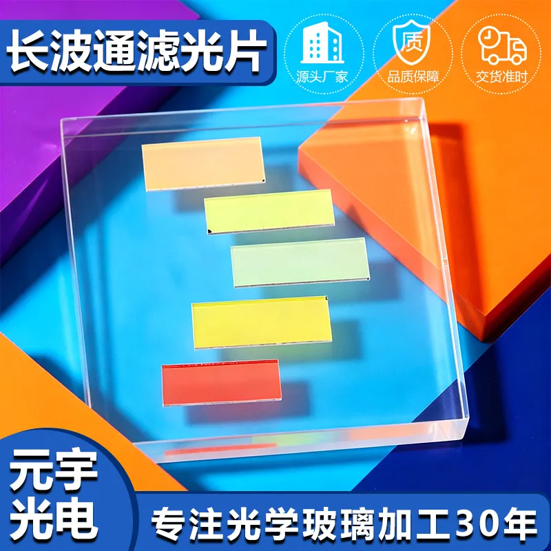
IR Filters in Machine Vision and Industrial Inspection
In machine vision and industrial inspection, that translates into a specific set of requirements rather than a general preference for quality. Machine vision decides whether a production line passes or stops, so its optics must be repeatable rather than merely good. Illumination wavelengths are chosen deliberately, filters must block exactly what the algorithm cannot tolerate, and any change in transmission or geometry becomes a false reject. The environment is often a factory floor with coolant mist, dust and vibration.
What drives cost and lead time
Layer count is the main cost lever. A simple IR-cut stack is a routine chamber run; adding a broadband AR on the second surface, a hydrophobic top layer, or tightening the transition from 30 nm to 10 nm each adds chamber time, increases sensitivity to layer thickness error and reduces yield, so prices rise faster than the layer count suggests. Substrate grade and thickness matter less than expected, except for sapphire, which is materially more expensive in every respect. Size is the second lever: parts that fit comfortably inside the chamber's uniform zone cost far less per unit than parts that must be positioned at the edge, where thickness uniformity degrades. In Machine Vision and Industrial Inspection, the cheapest real saving usually comes from relaxing the angle specification rather than from changing the material.
How IR filters works in practice
An IR filter removes a spectral band the sensor would otherwise record, and it does so in one of two ways. A dichroic filter reflects near-infrared light with a multilayer interference stack, so nothing is absorbed and the part stays cool; a blue or absorptive glass filter removes the same band by absorbing it in the bulk material. Dichroic designs give sharper edges, higher visible transmission and precisely tuneable cut-on wavelengths, but the edge moves with angle. Absorptive glass is angle-insensitive and cheap, but it is thicker, heavier and its cut-on is fixed by chemistry. In Machine Vision and Industrial Inspection, the choice usually comes down to how much of the field of view arrives off-axis: a narrow acceptance cone favors a dichroic design, while a wide-angle lens often needs an absorptive or a hybrid solution to avoid color shading across the frame.
Design rules that reduce cost
The design decisions that matter are the cut-on wavelength, the acceptance angle and the mounting. Place the cut-on where the sensor's quantum efficiency falls and its NIR sensitivity rises - most silicon sensors need the edge between 650 and 680 nm - and then decide how much of the aperture range must hold color accuracy. If the lens is fast or wide, either accept a wider transition or add an absorptive element. Leave a clear margin of at least 0.5 mm for mounting and a chamfer on both edges. Where the filter sits behind the lens rather than in front of it, remember that the ray bundle is no longer telecentric: the effective angle can exceed thirty degrees even in a modest system, which is exactly where a dichroic design begins to lose color fidelity in Machine Vision and Industrial Inspection.
Standards, documentation and traceability
IR filters are qualified through a mix of optical, environmental and compliance specifications. Drawings follow ISO 10110 for surface form and imperfections, and mechanical acceptance commonly cites MIL-PRF-13830B scratch-dig. Environmental durability is usually demonstrated with a humidity soak, a salt spray test, an abrasion test and an adhesion tape test, often against MIL-C-48497. Material compliance is documented through RoHS and REACH declarations. In Machine Vision and Industrial Inspection, additional requirements frequently arrive from the customer's own standards - automotive temperature ranges, medical cleaning regimes or outdoor UV exposure - and it is worth establishing those at quotation, because a coating that passes a humidity test can still fail a specific cleaning chemical.
Requirements specific to Machine Vision and Industrial Inspection
In machine vision and industrial inspection, that translates into a specific set of requirements rather than a general preference for quality. Machine vision decides whether a production line passes or stops, so its optics must be repeatable rather than merely good. Illumination wavelengths are chosen deliberately, filters must block exactly what the algorithm cannot tolerate, and any change in transmission or geometry becomes a false reject. The environment is often a factory floor with coolant mist, dust and vibration.
- Telecentric-friendly flatness and low wedge
- Band-matched coatings for the illumination wavelength
- Consistent transmission part to part
- Resistant to coolant, dust and cleaning solvents
ISO 10110 drawings, MIL-PRF-13830B surface quality, plus the machine builder's own repeatability and cleanliness requirements.
Selection data at a glance
| Parameter | Typical value | Notes |
|---|---|---|
| IR-cut cut-on | 630-700 nm | Tuned to the sensor response |
| Visible transmission | T ≥ 90 %, R ≤ 1 % | Average 420-620 nm |
| NIR blocking | OD2 - OD4 (1 % - 0.01 %) | 700-1100 nm |
| Edge steepness | 10-30 nm transition | Dichroic designs |
| Angle of incidence | 0-30 deg specified | Passband shifts blue with angle |
| Wavelength tolerance | ± 5 nm standard, ± 2 nm precision | Measured at stated AOI |
| Substrate | B270, D263T, blue glass, sapphire | Absorptive option removes NIR without angle shift |
| Thickness | 0.3-3 mm | 0.55 - 1.1 mm typical for camera windows |
| Environmental | Humidity, salt spray, abrasion tested | MIL-C-48497 / MIL-PRF-13830B |
Frequently asked questions
How tight can the wavelength tolerance be?
Plus or minus five nanometers is routine and plus or minus two nanometers is achievable on precision imaging parts. Tighter than that usually requires sorting parts by measurement, which raises cost sharply.
What cut-on wavelength should I specify?
Most silicon sensors need the cut-on between 650 and 680 nm, before the sensor's NIR response climbs. If the application also has an 850 nm illuminator nearby, tighten the blocking to OD3 and confirm the edge position against the source wavelength.
Why does my image look green at the corners?
That is angular shift. The dichroic edge moves toward shorter wavelengths as the angle of incidence increases, so off-axis rays lose blue light and the frame edges shift color. Solutions are a wider transition, an absorptive element, or moving the filter closer to the stop.
Need a quotation for ir filters?
Send your drawing, target specification or coating requirement and an optical engineer will reply within 24 hours with a price and a lead time.
Request a Quote Email an engineer