Failures in IR filters used in security and surveillance cameras tend to follow a small number of patterns, and each pattern has a signature. This article walks through the common failure modes, how to tell them apart with measurements rather than guesswork, and the process or design changes that actually remove the root cause.
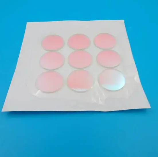
IR Filters in Security and Surveillance Cameras
In security and surveillance cameras, that translates into a specific set of requirements rather than a general preference for quality. Surveillance cameras run continuously, often outdoors, and must deliver usable images at night under near-infrared illumination. That combination makes IR-cut behavior and window durability the two defining requirements: the window has to pass the day spectrum faithfully, block infrared during daylight, and still transmit 850 nanometer illumination after dark on dual-mode designs.
Common failure modes and how they show up
Most IR filter failures are spectral drift, edge damage or delamination. Spectral drift after humidity exposure means the coating was deposited without adequate ion assistance; drift after temperature cycling points to a design that ignored the substrate's expansion. Delamination almost always starts at a chamfer or an uncoated margin and spreads inward. Ghosting or flare, which customers often report as a defect, is normally an optical design issue caused by an uncoated second surface reflecting back into the sensor. In Security and Surveillance Cameras, reproducible failures should be diagnosed by measuring the part before and after the environmental stress rather than only after, because that single comparison separates a coating problem from an assembly problem in one step.
Inspection and measurement
Spectral measurement is the primary inspection for an IR filter. A spectrophotometer covering 350 to 1100 nm will confirm cut-on wavelength, average visible transmission and blocking depth, and it should be measured at the specified angle - a part measured only at normal incidence can pass while failing in service. Beyond the spectrum, a color filter faces the same physical acceptance criteria as any window: surface quality in scratch-dig, edge chips, chamfer condition and cleanliness. Where the part is bonded or potted, a flatness or transmitted wavefront check matters as well. In Security and Surveillance Cameras, asking for a measured curve and an adhesion test result with the first article is what prevents a coating chemistry problem from turning into a field return six months later.
Coating and deposition considerations
Dichroic IR-cut designs run from roughly twenty to sixty layers of alternating high- and low-index oxides, with the layer thicknesses controlling both the position and the steepness of the edge. Ion-assisted deposition is the standard process because it produces dense layers that do not shift with humidity - an unassisted coating can move several nanometers after a week in a humid room. The residual reflection in the visible band has to be managed, since a strong reflection produces the green or magenta glint familiar on poorly coated camera windows; broadband AR layers are usually added on top of the dichroic stack to suppress it. For Security and Surveillance Cameras, also decide whether a hard, hydrophobic outer layer is required, because it changes both the durability and the price of the part.
Design rules that reduce cost
The design decisions that matter are the cut-on wavelength, the acceptance angle and the mounting. Place the cut-on where the sensor's quantum efficiency falls and its NIR sensitivity rises - most silicon sensors need the edge between 650 and 680 nm - and then decide how much of the aperture range must hold color accuracy. If the lens is fast or wide, either accept a wider transition or add an absorptive element. Leave a clear margin of at least 0.5 mm for mounting and a chamfer on both edges. Where the filter sits behind the lens rather than in front of it, remember that the ray bundle is no longer telecentric: the effective angle can exceed thirty degrees even in a modest system, which is exactly where a dichroic design begins to lose color fidelity in Security and Surveillance Cameras.
Handling, cleaning and packaging
The dichroic surface is both the optical function and the most vulnerable part of the component. Handle by the edge, never wipe dry, and clean only with the approved process: neutral detergent, cascaded deionised water rinses, then an alcohol or nitrogen dry. Fingerprints etch a hard oxide layer over time and create a permanent localised transmission dip that cannot be polished out. Storage uses particle-free interleaves and never stacks two coated faces together. Because the coating is a stack of thin layers, it is also sensitive to mechanical impact at the edge, so a chamfer is standard. In Security and Surveillance Cameras, the assembly process deserves equal attention: adhesives that outgas, or a potting compound that cures with shrinkage, can both shift the spectrum of a well-made part.
Requirements specific to Security and Surveillance Cameras
In security and surveillance cameras, that translates into a specific set of requirements rather than a general preference for quality. Surveillance cameras run continuously, often outdoors, and must deliver usable images at night under near-infrared illumination. That combination makes IR-cut behavior and window durability the two defining requirements: the window has to pass the day spectrum faithfully, block infrared during daylight, and still transmit 850 nanometer illumination after dark on dual-mode designs.
- IR-cut edge between 645 and 680 nm
- Outdoor-grade abrasion and salt spray resistance
- Hydrophobic topcoat for rain shedding
- Service life of five years or more with no transmission loss
IP-rated enclosure compatibility, MIL-style abrasion and humidity testing, RoHS and REACH declarations, and increasingly NDAA-related supply chain documentation.
Selection data at a glance
| Parameter | Typical value | Notes |
|---|---|---|
| IR-cut cut-on | 630-700 nm | Tuned to the sensor response |
| Visible transmission | T ≥ 90 %, R ≤ 1 % | Average 420-620 nm |
| NIR blocking | OD2 - OD4 (1 % - 0.01 %) | 700-1100 nm |
| Edge steepness | 10-30 nm transition | Dichroic designs |
| Angle of incidence | 0-30 deg specified | Passband shifts blue with angle |
| Wavelength tolerance | ± 5 nm standard, ± 2 nm precision | Measured at stated AOI |
| Substrate | B270, D263T, blue glass, sapphire | Absorptive option removes NIR without angle shift |
| Thickness | 0.3-3 mm | 0.55 - 1.1 mm typical for camera windows |
| Environmental | Humidity, salt spray, abrasion tested | MIL-C-48497 / MIL-PRF-13830B |
Frequently asked questions
Can you supply the filter laminated to a sensor window or a cover glass?
Yes, coating on thin substrates down to 0.3 mm allows direct lamination or bonding. State the adhesive or bonding method at quotation so the coating stress and the assembly thermal cycle can be considered together.
How tight can the wavelength tolerance be?
Plus or minus five nanometers is routine and plus or minus two nanometers is achievable on precision imaging parts. Tighter than that usually requires sorting parts by measurement, which raises cost sharply.
What cut-on wavelength should I specify?
Most silicon sensors need the cut-on between 650 and 680 nm, before the sensor's NIR response climbs. If the application also has an 850 nm illuminator nearby, tighten the blocking to OD3 and confirm the edge position against the source wavelength.
Need a quotation for ir filters?
Send your drawing, target specification or coating requirement and an optical engineer will reply within 24 hours with a price and a lead time.
Request a Quote Email an engineer