A part that measures correctly in the lab and fails in service is almost always a qualification gap rather than a manufacturing defect. This article sets out how laser cutting of glass is inspected and qualified for aerospace and defense optics, which standards apply, which tests reveal real weaknesses, and what documentation should travel with a shipment.
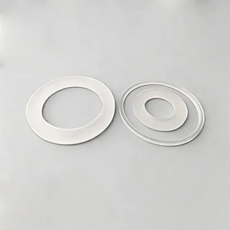
Laser Cutting of Glass in Aerospace and Defense Optics
In aerospace and defense optics, that translates into a specific set of requirements rather than a general preference for quality. Aerospace optics are qualified against thermal vacuum, vibration, shock and radiation environments, and once qualified they are difficult to change, which makes documentation and reproducibility the dominant requirement. Weight is critical, coatings must survive without moisture uptake, and every part carries a certification trail.
Inspection and measurement
Inspection after laser cutting concentrates on the edge, because that is where the process leaves its signature. A visual check under magnification for chips, cracks and discoloration is the first step; a cross-section or a micrograph confirms the absence of a heat-affected zone and subsurface damage. Dimensional verification uses an optical comparator or a vision system for outline and hole positions, and a profilometer or white-light interferometer for edge roughness and taper. For parts destined for optical coating, cleanliness and outgassing are also checked. In Aerospace and Defense Optics, the useful incoming test is a bend or thermal cycle on a sample from the batch, because edge damage that survives a visual check usually reveals itself under stress.
Standards, documentation and traceability
Laser-cut glass is qualified against the same drawing standards as any optical part, ISO 10110 and its associated imperfection standards, supplemented by specific requirements for edge chip size, roughness and taper. Where the part is used in a safety-relevant system, edge strength testing may be specified. Cleanliness and particle limits arrive from the customer's assembly environment, particularly in semiconductor and medical applications. Environmental compliance is documented through RoHS and REACH declarations. In Aerospace and Defense Optics, the documentation that most often matters is a process record identifying which cutting method was used, because it determines whether the edge can be reworked if the specification changes.
Common failure modes and how they show up
Laser cutting failures are edge failures. Thermal processing can leave micro-cracks that only propagate later, when the part is thermally cycled or mechanically loaded - a problem that shows up in the field rather than at inspection. Heat-affected zones reduce local strength and can produce a visible discoloration along the cut. Taper that exceeds specification causes fit problems in a slot or a frame. Contamination from the cutting process causes coating pinholes or bond-line defects. In Aerospace and Defense Optics, a part that passes dimensional inspection and fails in service is almost always a part whose edge was cut thermally and never inspected for micro-cracks, which is why the process should be chosen from the service environment rather than from the price list alone.
Handling, cleaning and packaging
Laser cutting produces parts with a clean edge but no protective chamfer, so the edges are thinner and sharper than a ground edge and chip easily if parts are stacked or poured into a bin. Parts are stored in trays with individual pockets, and any subsequent handling is edge-based. Thermal cutting can leave a very fine dust that must be removed before coating or bonding. Where the cut outline is complex, the parts should be kept in their original sheet until needed, since separating them early multiplies handling events. In Aerospace and Defense Optics, this is the practical reason laser cutting pairs well with thin, fragile, high-value parts: the process removes the mechanical forces, but everything that happens after the cut still has to respect how thin the material is.
Design rules that reduce cost
Laser cutting rewards drawings that suit the process. Keep cut edges away from optical surfaces, since a cut edge will never have the surface quality of a polished face. Design holes at least one material thickness from the edge and avoid narrow webs that will warp or break during handling. Internal corners should carry radii, because even a laser leaves a stress concentration at a sharp vertex. Where the part will be coated, restrict the coating to the aperture and leave the edge bare. Specify chip size and taper explicitly; if neither is stated, the shop will choose a process that meets the price rather than the application. For Aerospace and Defense Optics, a short note on the drawing about post-cut thermal or mechanical exposure is worth more than any tolerance, because it lets the process be selected correctly the first time.
Requirements specific to Aerospace and Defense Optics
In aerospace and defense optics, that translates into a specific set of requirements rather than a general preference for quality. Aerospace optics are qualified against thermal vacuum, vibration, shock and radiation environments, and once qualified they are difficult to change, which makes documentation and reproducibility the dominant requirement. Weight is critical, coatings must survive without moisture uptake, and every part carries a certification trail.
- Thermal vacuum and vibration survival
- Low weight with high specific stiffness
- Coating stability with no moisture shift
- Full first-article and process documentation
AS9100 quality systems, MIL specifications for coatings and surface quality, and customer-specific environmental qualification protocols.
Selection data at a glance
| Parameter | Typical capability | Notes |
|---|---|---|
| Cutting methods | CO2 thermal, ultrafast filamentation, scribe and break | Selected by thickness and edge spec |
| Kerf width | 20 - 100 micrometers (ultrafast) | CO2 is wider, water-assisted narrower |
| Edge quality | no micro-cracks with ultrafast, Ra < 1 micrometer | Thermal methods leave a heat-affected zone |
| Thickness range | 0.05-20 mm | Ultrafast preferred below 1 mm |
| Outline tolerance | ±0.05 mm typical, ±0.02 mm on small parts | Complex contours without tooling |
| Edge chips | ≤ 0.02 mm with ultrafast | CO2 needs post-processing |
| Taper | < 5 micrometers per 100 micrometers of depth | Ultrafast, low-taper |
| Set-up cost | none - no hard tooling | Economical from one piece |
| Ideal for | thin glass, tempered glass, complex outlines, wafers | Also drills holes and slots |
Frequently asked questions
Does laser cutting leave micro-cracks?
It depends on the process. Ultrafast filamentation cutting produces an edge with no micro-cracks and chips below 0.02 mm. CO2 thermal cutting leaves a heat-affected zone and requires edge grinding or polishing if the part will be stressed.
Can you cut chemically strengthened glass?
Yes, and ultrafast filamentation is the preferred method because it introduces very little heat and preserves the compressive surface layer better than thermal cutting. Cutting before strengthening is the more robust sequence when the geometry allows.
How accurate is laser cutting compared with machining?
Outline tolerance of plus or minus 0.05 mm is routine and plus or minus 0.02 mm is achievable on small parts, with the significant advantage of no hard tooling. The trade is edge quality: a machined edge can be chamfered and polished, a laser-cut edge is as cut.
Need a quotation for laser cutting of glass?
Send your drawing, target specification or coating requirement and an optical engineer will reply within 24 hours with a price and a lead time.
Request a Quote Email an engineer