Optical encoder scales and reticles are glass parts carrying fine gratings or patterns that a sensor reads, and the cut edge or kerf has to be clean enough not to scatter light into the read head. A laser cut that leaves micro-cracks or debris can quietly wreck the signal. This guide covers the failure modes that break the optical readout and the practical fixes that keep the cut crisp.
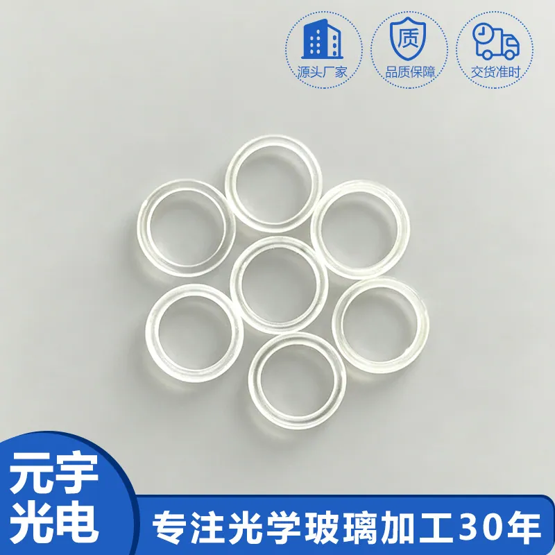
Laser Cutting of Glass in Laser Cutting for Optical Encoder Scales and Reticles
In an encoder scale or reticle the glass substrate carries a patterned feature the sensor reads, so the laser's job is to shape the part without disturbing the optical edge or leaving residue that scatters light. The cut is part of the optical path, which means edge quality matters more than it would on a cosmetic pane. The process is chosen for a debris-free, low-stress kerf rather than raw cut speed.
Common failure modes and how they show up
The usual failures are micro-cracks along the edge that later propagate, recast or debris on the surface that scatters light into the read head, and a heat-affected zone that changes the local index or stresses the pattern. They appear as a noisy or intermittent encoder signal, a reticle with stray scatter, or a part that fractures in handling. Because the symptom is a signal error, the cut is the last thing blamed.
Inspection and measurement
Verify the cut by inspecting the edge under sufficient magnification for cracks and debris, and by checking the part optically for scatter where the read head looks. A dimensional check of the kerf and the feature position confirms the pattern was not shifted by thermal load, and a clean-room wipe test confirms no loose debris remains. The measurement that matters is the edge the sensor sees, not the cut speed.
Coating and deposition considerations
When the scale carries an anti-reflective or patterned coating, the laser pass has to avoid damaging it or leaving a halo at the edge that the read head interprets as a feature. The process window is tuned so the beam cuts the glass without ablating or discolouring the adjacent coating, and any edge seal is applied after cutting, not before. State the coating the part carries, because a bare substrate and a coated one cut on different windows.
Design rules that reduce cost
Cost stays down when the feature density and the edge quality are specified to what the read head needs, not a round-number finish, and when the substrate thickness is chosen for stable handling rather than minimal material. A simple fixture and a standard pattern pitch reduce setup, and qualifying the cut to the actual signal spec avoids paying for an edge quality no encoder uses. The economical part is the one whose cut was written for the read head, not borrowed from a generic glass-cut job.
How it compares with the alternatives
Compared with mechanical scribing or water-jet cutting, laser cutting gives a finer, debris-controllable kerf but needs a tighter process window to avoid micro-cracks; compared with etching the outline, it is faster for low volumes and kinder to a coated part. The right choice is the method that yields a clean, low-stress edge at the volume and tolerance the encoder demands. When the readout is sensitive, the edge quality, not the cut rate, decides the method.
Requirements specific to Laser Cutting for Optical Encoder Scales and Reticles
Readout duty puts the edge quality and the debris on the signal path, so those lead the specification. Choose a process window that yields a debris-free, low-stress kerf, inspect the edge for cracks and scatter, and cut before any edge coating or seal. Treat the cut as an optical edge, qualified against the read-head signal, not a mechanical trim.
- Process window for debris-free kerf
- Edge inspected for cracks and scatter
- Low-stress cut avoids propagation
- Coating cut without halo or damage
- Feature position held thermally
- Edge quality to read-head spec
Framework references: edge quality, micro-crack and dimensional limits per ISO 10110, read as design targets for the encoder's signal budget. Environmental declarations such as RoHS are the supplier's to state against the current official text, not to be assumed for a precision component.
Selection data at a glance
| Parameter | Typical capability | Notes |
|---|---|---|
| Edge | Debris-free kerf | Signal |
| Cracks | Inspected, low stress | Life |
| Scatter | Optical check | Read head |
| Coating | Cut without halo | Pattern |
| Position | Held thermally | Feature |
| Spec | To read head | Quality |
Frequently asked questions
Why does my encoder signal get noisy even though the cut looks clean?
Because the failure is usually micro-cracks along the edge or fine debris that scatters light into the read head, neither of which is obvious to the eye. Both add noise or intermittent dropouts to the signal while the cut appears tidy. Inspect the edge under magnification and check optically for scatter.
Can laser cutting damage the encoder coating?
It can if the process window is wrong, leaving a halo or discolouration at the edge that the read head reads as a false feature. The beam is tuned to cut the glass without ablating the adjacent coating, and any edge seal goes on after cutting.
Is laser cutting better than scribing for scales?
For fine, debris-sensitive encoder edges it usually is, because the kerf is controllable and clean, but it demands a tighter process window to avoid micro-cracks. Scribing is cheaper for crude outlines; laser earns its place where the edge is part of the optical readout.
Need a quotation for laser cutting of glass?
Send your drawing, target specification or coating requirement and an optical engineer will reply within 24 hours with a price and a lead time.
Request a Quote Email an engineer