Specifying laser cutting of glass for machine vision and industrial inspection is largely a matter of deciding which three numbers actually govern the application and letting the rest follow. This guide walks through the parameters that belong on the drawing, the tolerances that genuinely change the price, and the specification items that are routinely left out and then argued about at first article.
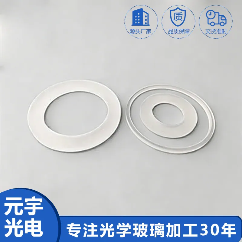
Laser Cutting of Glass in Machine Vision and Industrial Inspection
In machine vision and industrial inspection, that translates into a specific set of requirements rather than a general preference for quality. Machine vision decides whether a production line passes or stops, so its optics must be repeatable rather than merely good. Illumination wavelengths are chosen deliberately, filters must block exactly what the algorithm cannot tolerate, and any change in transmission or geometry becomes a false reject. The environment is often a factory floor with coolant mist, dust and vibration.
Coating and deposition considerations
Cutting and coating interact in two directions. First, a laser-cut edge must be clean and free of contamination before coating, because a cracked or heat-damaged edge will outgas in the chamber and produce coating defects around the perimeter. Second, if the part is coated before cutting, most laser processes will damage the coating near the cut line, so coated-then-cut is generally limited to processes where the coating is removed from the cut zone and the edge is subsequently cleaned. For Machine Vision and Industrial Inspection, the reliable sequence is cut first, finish the edge, clean, then coat - and to state in the drawing that the coating covers the optical aperture only, leaving any cut edge bare so that edge preparation is not compromised.
How laser cutting of glass works in practice
Laser cutting removes material with light rather than with a wheel, and for glass that changes the economics as well as the quality. There is no hard tooling, so a new outline costs a drawing rather than a mold, and there is no tool wear, so the hundred-thousandth part is cut the same way as the first. Three methods dominate. A CO2 laser heats the glass until it fractures along a controlled path, which is fast and cheap but leaves a heat-affected zone and microscopic cracks. Ultrafast lasers in the picosecond or femtosecond range focus inside the material and create a filament that modifies the glass along a line, after which a small force separates the part - the result is a clean edge with no micro-cracks. Scribe-and-break sits between the two, using a shallow score followed by mechanical separation. In Machine Vision and Industrial Inspection, the choice is usually set by edge quality and by whether the part must survive subsequent thermal or mechanical stress.
The tolerances that actually matter
Laser cutting is specified on outline accuracy, edge quality and taper. Outline tolerance of plus or minus 0.05 mm is routine and plus or minus 0.02 mm is achievable on small parts, without the tooling costs that a machined profile would require. Edge quality is the differentiator: ultrafast cutting produces chips under 0.02 mm and an edge roughness below a micrometer, while thermal methods leave a heat-affected zone that is normally removed by grinding or polishing. Taper, the difference in kerf width between the entry and exit faces, is significant for thick parts and is smallest with ultrafast processing. In Machine Vision and Industrial Inspection, the number that most often decides the process is the permitted edge chip size, since it determines whether the part can be used straight from the laser or needs a finishing step.
Design rules that reduce cost
Laser cutting rewards drawings that suit the process. Keep cut edges away from optical surfaces, since a cut edge will never have the surface quality of a polished face. Design holes at least one material thickness from the edge and avoid narrow webs that will warp or break during handling. Internal corners should carry radii, because even a laser leaves a stress concentration at a sharp vertex. Where the part will be coated, restrict the coating to the aperture and leave the edge bare. Specify chip size and taper explicitly; if neither is stated, the shop will choose a process that meets the price rather than the application. For Machine Vision and Industrial Inspection, a short note on the drawing about post-cut thermal or mechanical exposure is worth more than any tolerance, because it lets the process be selected correctly the first time.
Requirements specific to Machine Vision and Industrial Inspection
In machine vision and industrial inspection, that translates into a specific set of requirements rather than a general preference for quality. Machine vision decides whether a production line passes or stops, so its optics must be repeatable rather than merely good. Illumination wavelengths are chosen deliberately, filters must block exactly what the algorithm cannot tolerate, and any change in transmission or geometry becomes a false reject. The environment is often a factory floor with coolant mist, dust and vibration.
- Telecentric-friendly flatness and low wedge
- Band-matched coatings for the illumination wavelength
- Consistent transmission part to part
- Resistant to coolant, dust and cleaning solvents
ISO 10110 drawings, MIL-PRF-13830B surface quality, plus the machine builder's own repeatability and cleanliness requirements.
Selection data at a glance
| Parameter | Typical capability | Notes |
|---|---|---|
| Cutting methods | CO2 thermal, ultrafast filamentation, scribe and break | Selected by thickness and edge spec |
| Kerf width | 20 - 100 micrometers (ultrafast) | CO2 is wider, water-assisted narrower |
| Edge quality | no micro-cracks with ultrafast, Ra < 1 micrometer | Thermal methods leave a heat-affected zone |
| Thickness range | 0.05-20 mm | Ultrafast preferred below 1 mm |
| Outline tolerance | ±0.05 mm typical, ±0.02 mm on small parts | Complex contours without tooling |
| Edge chips | ≤ 0.02 mm with ultrafast | CO2 needs post-processing |
| Taper | < 5 micrometers per 100 micrometers of depth | Ultrafast, low-taper |
| Set-up cost | none - no hard tooling | Economical from one piece |
| Ideal for | thin glass, tempered glass, complex outlines, wafers | Also drills holes and slots |
Frequently asked questions
Do I need to specify the cutting method?
You should specify the outcome - chip size, taper, edge roughness and post-cut service conditions - and let the process follow from that. Naming a method without stating the requirement often produces an edge that measures correctly and fails in the field.
Does laser cutting leave micro-cracks?
It depends on the process. Ultrafast filamentation cutting produces an edge with no micro-cracks and chips below 0.02 mm. CO2 thermal cutting leaves a heat-affected zone and requires edge grinding or polishing if the part will be stressed.
Can you cut chemically strengthened glass?
Yes, and ultrafast filamentation is the preferred method because it introduces very little heat and preserves the compressive surface layer better than thermal cutting. Cutting before strengthening is the more robust sequence when the geometry allows.
Need a quotation for laser cutting of glass?
Send your drawing, target specification or coating requirement and an optical engineer will reply within 24 hours with a price and a lead time.
Request a Quote Email an engineer