Failures in laser cutting of glass used in robotics and factory automation tend to follow a small number of patterns, and each pattern has a signature. This article walks through the common failure modes, how to tell them apart with measurements rather than guesswork, and the process or design changes that actually remove the root cause.
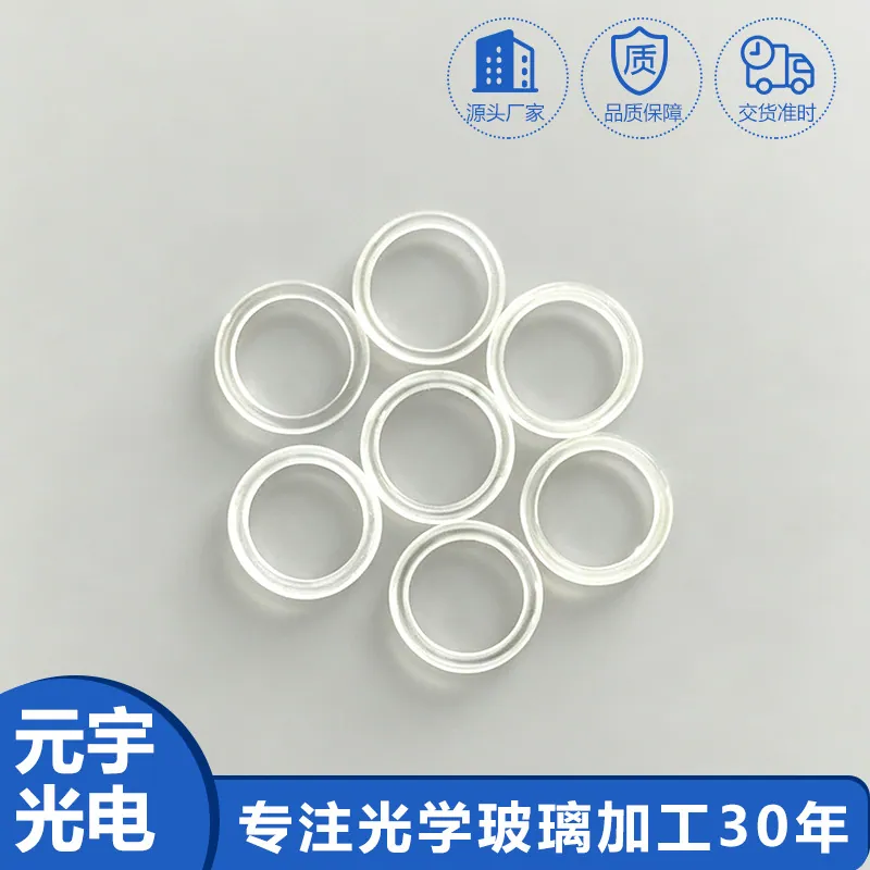
Laser Cutting of Glass in Robotics and Factory Automation
In robotics and factory automation, that translates into a specific set of requirements rather than a general preference for quality. Robots and automated cells use optical components continuously in environments built for metal, not glass: coolant, swarf, vibration and cleaning chemicals. Sensors and vision windows must survive being wiped, bumped and hosed down, while maintaining the repeatability the control system assumes.
Design rules that reduce cost
Laser cutting rewards drawings that suit the process. Keep cut edges away from optical surfaces, since a cut edge will never have the surface quality of a polished face. Design holes at least one material thickness from the edge and avoid narrow webs that will warp or break during handling. Internal corners should carry radii, because even a laser leaves a stress concentration at a sharp vertex. Where the part will be coated, restrict the coating to the aperture and leave the edge bare. Specify chip size and taper explicitly; if neither is stated, the shop will choose a process that meets the price rather than the application. For Robotics and Factory Automation, a short note on the drawing about post-cut thermal or mechanical exposure is worth more than any tolerance, because it lets the process be selected correctly the first time.
Common failure modes and how they show up
Laser cutting failures are edge failures. Thermal processing can leave micro-cracks that only propagate later, when the part is thermally cycled or mechanically loaded - a problem that shows up in the field rather than at inspection. Heat-affected zones reduce local strength and can produce a visible discoloration along the cut. Taper that exceeds specification causes fit problems in a slot or a frame. Contamination from the cutting process causes coating pinholes or bond-line defects. In Robotics and Factory Automation, a part that passes dimensional inspection and fails in service is almost always a part whose edge was cut thermally and never inspected for micro-cracks, which is why the process should be chosen from the service environment rather than from the price list alone.
Inspection and measurement
Inspection after laser cutting concentrates on the edge, because that is where the process leaves its signature. A visual check under magnification for chips, cracks and discoloration is the first step; a cross-section or a micrograph confirms the absence of a heat-affected zone and subsurface damage. Dimensional verification uses an optical comparator or a vision system for outline and hole positions, and a profilometer or white-light interferometer for edge roughness and taper. For parts destined for optical coating, cleanliness and outgassing are also checked. In Robotics and Factory Automation, the useful incoming test is a bend or thermal cycle on a sample from the batch, because edge damage that survives a visual check usually reveals itself under stress.
Coating and deposition considerations
Cutting and coating interact in two directions. First, a laser-cut edge must be clean and free of contamination before coating, because a cracked or heat-damaged edge will outgas in the chamber and produce coating defects around the perimeter. Second, if the part is coated before cutting, most laser processes will damage the coating near the cut line, so coated-then-cut is generally limited to processes where the coating is removed from the cut zone and the edge is subsequently cleaned. For Robotics and Factory Automation, the reliable sequence is cut first, finish the edge, clean, then coat - and to state in the drawing that the coating covers the optical aperture only, leaving any cut edge bare so that edge preparation is not compromised.
Requirements specific to Robotics and Factory Automation
In robotics and factory automation, that translates into a specific set of requirements rather than a general preference for quality. Robots and automated cells use optical components continuously in environments built for metal, not glass: coolant, swarf, vibration and cleaning chemicals. Sensors and vision windows must survive being wiped, bumped and hosed down, while maintaining the repeatability the control system assumes.
- Impact and abrasion tolerance for a factory floor
- Repeatable optical performance over millions of cycles
- Solvent and coolant resistance
- Compact outline with simple mounting geometry
ISO 10218 context for robotic safety, ISO 10110 drawings, and customer-specific environmental test protocols.
Selection data at a glance
| Parameter | Typical capability | Notes |
|---|---|---|
| Cutting methods | CO2 thermal, ultrafast filamentation, scribe and break | Selected by thickness and edge spec |
| Kerf width | 20 - 100 micrometers (ultrafast) | CO2 is wider, water-assisted narrower |
| Edge quality | no micro-cracks with ultrafast, Ra < 1 micrometer | Thermal methods leave a heat-affected zone |
| Thickness range | 0.05-20 mm | Ultrafast preferred below 1 mm |
| Outline tolerance | ±0.05 mm typical, ±0.02 mm on small parts | Complex contours without tooling |
| Edge chips | ≤ 0.02 mm with ultrafast | CO2 needs post-processing |
| Taper | < 5 micrometers per 100 micrometers of depth | Ultrafast, low-taper |
| Set-up cost | none - no hard tooling | Economical from one piece |
| Ideal for | thin glass, tempered glass, complex outlines, wafers | Also drills holes and slots |
Frequently asked questions
Can laser cutting drill holes as well as outlines?
Yes. Holes, slots and internal apertures are all produced in the same pass, with the smallest practical diameter determined by thickness and by the process chosen. Complex internal geometry is one of the main reasons to use a laser.
What thickness range can be cut?
From about 0.05 mm ultra-thin glass up to 20 mm, though the process changes with thickness. Ultrafast processing is preferred below approximately 1 mm, and thermal or hybrid methods are more economical for thicker material.
Do I need to specify the cutting method?
You should specify the outcome - chip size, taper, edge roughness and post-cut service conditions - and let the process follow from that. Naming a method without stating the requirement often produces an edge that measures correctly and fails in the field.
Need a quotation for laser cutting of glass?
Send your drawing, target specification or coating requirement and an optical engineer will reply within 24 hours with a price and a lead time.
Request a Quote Email an engineer