Cover and touch-sensor glass is cut to shape with lasers that avoid the edge chipping of mechanical methods, and as panels get thinner and corner-heavy the cut edge becomes the yield-limiting step. A poorly controlled cut leaves micro-cracks that later fail under flex or impact, which is exactly the failure a touch device cannot afford. This troubleshooting note covers the failure modes that ruin edges and the practical fixes that keep yield up for touch-sensor and cover glass substrates.
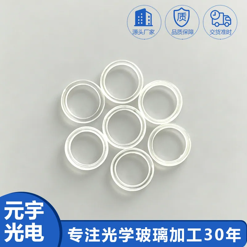
Laser Cutting of Glass in Touch-Sensor and Cover Glass Substrates
In a cover-glass line the laser separates the panel from the sheet and defines the edge the user never sees but the device depends on, because a cracked edge propagates under the constant flex of a touch screen. The cut is usually an ultra-short-pulse or controlled-scoring process that localizes the damage instead of fracturing the whole sheet, and the edge quality it leaves is the number that decides downstream yield. The failure modes are about how much hidden damage the cut leaves behind.
Common failure modes and how they show up
The usual failures are micro-cracks along the edge from too much pulse energy, residual stress that makes the corner fail later under drop, and thermal hazing or melting on thin panels from a process tuned too hot. They show up as a panel that passes the line but cracks in drop testing, an edge that flakes during bonding, or a hazy cut line that fails appearance. Because the damage is subsurface, the first sign is often a field return rather than a line rejection.
Inspection and measurement
The fix starts with edge inspection under magnification and, where needed, a stress or strength test rather than a visual pass, because the defects that matter are subsurface and invisible to the eye. Map edge quality along the contour, especially at corners where stress concentrates, and correlate it with the cut parameters that produced it. Regular edge-strength sampling is what turns a hidden crack into a caught event before the panel ships.
Coating and deposition considerations
Many cover glasses carry an AR or anti-fingerprint coating that the laser must not damage at the cut edge, because a burnt or delaminated edge coating reads as a defect and can lift during bonding. The process is tuned so the beam affects only the glass at the kerf and the coating just inside the edge stays intact, which means controlling pulse energy and spot size at the contour rather than over the whole surface. State the edge coating condition as part of the acceptance, not as an afterthought.
Design rules that reduce cost
Cost is kept down by tuning the cut to the thinnest panel the design allows and by avoiding exotic contours that need slow, multi-pass cutting, because corner-heavy shapes spend disproportionate time at the laser. Holding the pulse parameters in a tight window reduces scrap from micro-cracks, and designing radii instead of sharp corners lets the process keep edge quality where stress would otherwise concentrate. The cheap cut is the one whose parameters were written for the panel, not copied from a thicker part.
How it compares with the alternatives
Against mechanical cutting and grinding, laser cutting avoids the chipping and the separate edge-grind step but demands tighter process control to avoid hidden cracks, while a score-and-break route is cheap but leaves a rougher edge that needs finishing. Laser wins on edge quality and complexity of shape, mechanical wins on raw throughput for simple rectangles. The right route is the one whose edge quality still clears the drop and flex targets at an acceptable scrap rate.
Requirements specific to Touch-Sensor and Cover Glass Substrates
Touch duty adds flex, drop and bonding to the usual cutting constraints, so subsurface edge quality and corner stress lead the specification. Choose a cut process that localizes damage, inspect the edge under magnification with strength sampling, and keep the edge coating intact at the kerf. Require edge-strength correlation to cut parameters rather than a visual pass, because a touch panel that passes the line can still crack in drop testing if the cut left a hidden crack.
- Damage-localizing cut process
- Edge inspected, strength sampled
- Corner stress controlled
- Edge coating intact at kerf
- Parameters tuned to panel
- Radii over sharp corners
Framework references: edge and surface limits per ISO 10110, with edge-strength acceptance stated against the device's own drop and flex specification. Environmental declarations such as RoHS are the supplier's to state against the current official text.
Selection data at a glance
| Parameter | Typical capability | Notes |
|---|---|---|
| Process | Ultra-short pulse | Localize |
| Edge | Inspected, sampled | Strength |
| Corner | Stress controlled | Drop |
| Coating | Intact at kerf | Bond |
| Params | Tuned to panel | Scrap |
| Shape | Radii preferred | Cost |
Frequently asked questions
Why does a visually fine cut still fail drop testing?
Because the failure is a subsurface micro-crack or residual stress the eye cannot see, and a touch panel flexes constantly so that hidden damage propagates under use or impact. Edge inspection under magnification with strength sampling is what catches it before shipping.
Does the edge coating matter to the laser cut?
Yes, because a burnt or delaminated edge coating reads as a defect and can lift during bonding. The process has to affect only the glass at the kerf so the coating just inside the edge stays intact, which is why pulse energy and spot size at the contour are controlled.
What is the cheapest way to cut cover glass well?
Tune the cut to the thinnest panel the design allows, use radii instead of sharp corners so stress does not concentrate, and hold the pulse parameters in a tight window to avoid scrap from micro-cracks.
Need a quotation for laser cutting of glass?
Send your drawing, target specification or coating requirement and an optical engineer will reply within 24 hours with a price and a lead time.
Request a Quote Email an engineer