Failures in lens protection windows used in machine vision and industrial inspection tend to follow a small number of patterns, and each pattern has a signature. This article walks through the common failure modes, how to tell them apart with measurements rather than guesswork, and the process or design changes that actually remove the root cause.
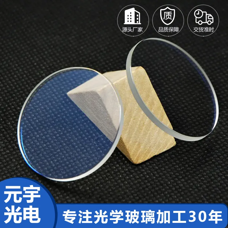
Lens Protection Windows in Machine Vision and Industrial Inspection
In machine vision and industrial inspection, that translates into a specific set of requirements rather than a general preference for quality. Machine vision decides whether a production line passes or stops, so its optics must be repeatable rather than merely good. Illumination wavelengths are chosen deliberately, filters must block exactly what the algorithm cannot tolerate, and any change in transmission or geometry becomes a false reject. The environment is often a factory floor with coolant mist, dust and vibration.
Design rules that reduce cost
Design decisions center on exposure and mounting. Decide what the window will meet - rain, salt, sand, cleaning chemicals, a gloved hand - and pick substrate and coating accordingly. Keep the optical aperture inside the coated area and leave a clear, uncoated margin of 0.5 to 1 millimeter for gaskets and adhesives so that sealing pressure never sits on a coating. Specify the chamfer. If the window also carries an IR-cut or bandpass function, confirm that the coating is deposited on the correct face, since reversing front and back is a classic first-article error. In Machine Vision and Industrial Inspection, the aim is a part that is optically invisible and mechanically unremarkable, which is exactly what makes it easy to specify badly.
Common failure modes and how they show up
The field failures are recognisable: haze from abrasion, smeared coating from aggressive cleaning, water spotting that has etched the surface, delamination beginning at the edge, and cracking from over-tight clamping or thermal shock. Optical failures such as flare or ghosting usually indicate an uncoated inner face or a coating band that does not cover the illumination wavelength. In Machine Vision and Industrial Inspection, the useful diagnostic is location: damage concentrated at the center suggests abrasion or cleaning, damage at the edge suggests clamping or sealing, and a uniform gray veil suggests a coating deposition problem rather than anything the user did.
Inspection and measurement
Inspection covers optical performance and durability in equal measure. Transmission and reflectance are measured over the sensor band, haze on a haze meter, and flatness or transmitted wavefront on an interferometer. Durability is verified with abrasion, cross-hatch adhesion, humidity soak and salt spray, with water contact angle checked when a hydrophobic layer is specified. Dimensional checks confirm outline, thickness, chamfer and edge quality, and where the part carries a printed or coated feature, registration is measured as well. In Machine Vision and Industrial Inspection, the test that most often reveals a weak part is not the optical measurement but the environmental sequence: humidity followed by abrasion, because that combination finds adhesion problems that neither test finds alone.
Coating and deposition considerations
The standard coating is a broadband anti-reflective layer on both faces, tuned to the sensor band rather than to the visible alone. That detail matters more than it appears: a visible-only AR coating on a window in front of an 850 nm illuminator will reflect the illumination back into the system and produce flare. Beyond AR, functional layers are usually added - a hard outer layer for abrasion, a hydrophobic and oleophobic top layer so that rain and fingerprints shed rather than smear, and sometimes an anti-static layer to reduce dust attraction. Many protection windows also carry a functional coating on the inner face, most commonly IR-cut, which lets one part do two jobs. In Machine Vision and Industrial Inspection, the combination that gives the best field reliability is usually dual-sided AR plus a hydrophobic topcoat on a sapphire or hard-coated borosilicate substrate.
Requirements specific to Machine Vision and Industrial Inspection
In machine vision and industrial inspection, that translates into a specific set of requirements rather than a general preference for quality. Machine vision decides whether a production line passes or stops, so its optics must be repeatable rather than merely good. Illumination wavelengths are chosen deliberately, filters must block exactly what the algorithm cannot tolerate, and any change in transmission or geometry becomes a false reject. The environment is often a factory floor with coolant mist, dust and vibration.
- Telecentric-friendly flatness and low wedge
- Band-matched coatings for the illumination wavelength
- Consistent transmission part to part
- Resistant to coolant, dust and cleaning solvents
ISO 10110 drawings, MIL-PRF-13830B surface quality, plus the machine builder's own repeatability and cleanliness requirements.
Selection data at a glance
| Parameter | Typical value | Notes |
|---|---|---|
| Transmission | T ≥ 98 % with dual-sided AR | Per the sensor band |
| Substrate | B270, borosilicate, sapphire, quartz | Sapphire for abrasive environments |
| Thickness | 0.3-5 mm | 0.5 - 1.1 mm typical for camera windows |
| Haze | ≤ 0.2 %, typically ≤ 0.05 % | Critical for imaging |
| Hardness | 9H pencil, 0000 steel wool pass | Hard oxide or sapphire |
| Water contact angle | >= 100 deg with hydrophobic layer | Rain and fingerprint shedding |
| Environmental | salt spray, 85/85 humidity, UV, -40 to +105 °C | Grade depends on exposure |
| Outline tolerance | ± 0.05 mm, laser-cut shapes available | Chamfer 0.1 - 0.3 mm |
| Options | IR-cut or bandpass function integrated | One window, two jobs |
Frequently asked questions
Which face should the functional coating go on?
Functional coatings belong on the inner face where they are protected. Reversing front and back is a common first-article error, so the drawing should state explicitly which surface faces the sensor and which faces the environment.
Does a protection window degrade image quality?
Not if it is specified properly. Dual-sided AR keeps transmission above 98 percent, and flatness plus parallelism control keeps the window optically neutral. Quality loss usually comes from an uncoated inner face or from a coating band that misses the illumination wavelength.
When is sapphire worth the extra cost?
When the surface will be repeatedly touched, dragged or exposed to abrasive particles, and when the window is a sealed rather than serviceable component. For protected indoor equipment, hard-coated borosilicate is usually sufficient.
Need a quotation for lens protection windows?
Send your drawing, target specification or coating requirement and an optical engineer will reply within 24 hours with a price and a lead time.
Request a Quote Email an engineer