Specifying lens protection windows for projection and display systems is largely a matter of deciding which three numbers actually govern the application and letting the rest follow. This guide walks through the parameters that belong on the drawing, the tolerances that genuinely change the price, and the specification items that are routinely left out and then argued about at first article.
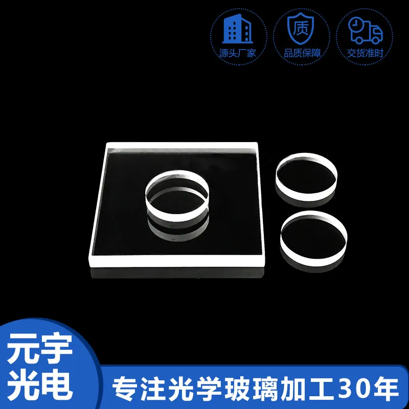
Lens Protection Windows in Projection and Display Systems
In projection and display systems, that translates into a specific set of requirements rather than a general preference for quality. Projection and display paths put several coated surfaces between the light source and the viewer, so each surface has to be both highly transmissive and color neutral. Ghost images caused by an uncoated rear surface are the recurring complaint, and in laser-illuminated projectors the coating must also handle speckle-sensitive coherence and higher flux.
Design rules that reduce cost
Design decisions center on exposure and mounting. Decide what the window will meet - rain, salt, sand, cleaning chemicals, a gloved hand - and pick substrate and coating accordingly. Keep the optical aperture inside the coated area and leave a clear, uncoated margin of 0.5 to 1 millimeter for gaskets and adhesives so that sealing pressure never sits on a coating. Specify the chamfer. If the window also carries an IR-cut or bandpass function, confirm that the coating is deposited on the correct face, since reversing front and back is a classic first-article error. In Projection and Display Systems, the aim is a part that is optically invisible and mechanically unremarkable, which is exactly what makes it easy to specify badly.
Coating and deposition considerations
The standard coating is a broadband anti-reflective layer on both faces, tuned to the sensor band rather than to the visible alone. That detail matters more than it appears: a visible-only AR coating on a window in front of an 850 nm illuminator will reflect the illumination back into the system and produce flare. Beyond AR, functional layers are usually added - a hard outer layer for abrasion, a hydrophobic and oleophobic top layer so that rain and fingerprints shed rather than smear, and sometimes an anti-static layer to reduce dust attraction. Many protection windows also carry a functional coating on the inner face, most commonly IR-cut, which lets one part do two jobs. In Projection and Display Systems, the combination that gives the best field reliability is usually dual-sided AR plus a hydrophobic topcoat on a sapphire or hard-coated borosilicate substrate.
How lens protection windows works in practice
A lens protection window is the transparent barrier between a lens or sensor and the outside world. Its job is to keep water, dust, salt, fingerprints and impact away from the optical surfaces behind it while changing the light as little as possible. That sounds trivial and is not: every extra surface introduces reflection, every coating introduces scatter, and every mechanical mounting decision changes the wavefront. The design target is therefore a window that measures at or above the transmission of bare glass while remaining optically neutral, and that survives the environment it is exposed to. In Projection and Display Systems, the window is frequently also the first element of the optical system, so its flatness, thickness uniformity and coating quality are part of the imaging chain rather than generic protection.
The tolerances that actually matter
A protection window is specified on transmission, flatness and thickness uniformity, in that order. Transmission should be quoted with the coating: above 98 percent is normal for dual-sided AR in the visible. Flatness and parallelism matter because the window sits in the imaging path - a wedge steers the beam, and a curved surface shifts the focal plane, so a few arcminutes of wedge can be significant in a long focal length system. Thickness tolerance matters for the same reason and also for sealing. Haze is a separate specification and should never be left implicit, because a coated part with excellent transmission and one percent haze looks like a dirty lens. In Projection and Display Systems, add a required abrasion resistance and, where relevant, a water contact angle for hydrophobic coatings.
Substrate and material selection
Substrate choice follows exposure. B270 and ultra-clear float glass are adequate for indoor equipment and protected outdoor installations. Borosilicate adds thermal stability for parts exposed to sunlight or heat. Sapphire is the choice when the surface will be touched, dragged or abraded, and it also transmits further into the infrared, but it costs several times more and is harder to finish. Quartz appears where the spectral band reaches into the ultraviolet. Thickness is a mechanical decision with an optical consequence: thicker windows resist impact and sealing pressure better, but they add mass, cost and thermal inertia, and on a fast optical system they can shift focus. In Projection and Display Systems, the most common specification error is using float glass where the part will be exposed to abrasion, and the most common cost error is using sapphire where nothing will ever touch it.
Requirements specific to Projection and Display Systems
In projection and display systems, that translates into a specific set of requirements rather than a general preference for quality. Projection and display paths put several coated surfaces between the light source and the viewer, so each surface has to be both highly transmissive and color neutral. Ghost images caused by an uncoated rear surface are the recurring complaint, and in laser-illuminated projectors the coating must also handle speckle-sensitive coherence and higher flux.
- Transmission above 98 percent with dual-sided AR
- Color-neutral residual reflection
- Dichroic accuracy for color splitting within ±5 nm
- Thermal stability through lamp or laser heating
ISO 10110 drawings, ISO 9241 context for display ergonomics, and RoHS and REACH declarations.
Selection data at a glance
| Parameter | Typical value | Notes |
|---|---|---|
| Transmission | T ≥ 98 % with dual-sided AR | Per the sensor band |
| Substrate | B270, borosilicate, sapphire, quartz | Sapphire for abrasive environments |
| Thickness | 0.3-5 mm | 0.5 - 1.1 mm typical for camera windows |
| Haze | ≤ 0.2 %, typically ≤ 0.05 % | Critical for imaging |
| Hardness | 9H pencil, 0000 steel wool pass | Hard oxide or sapphire |
| Water contact angle | >= 100 deg with hydrophobic layer | Rain and fingerprint shedding |
| Environmental | salt spray, 85/85 humidity, UV, -40 to +105 °C | Grade depends on exposure |
| Outline tolerance | ± 0.05 mm, laser-cut shapes available | Chamfer 0.1 - 0.3 mm |
| Options | IR-cut or bandpass function integrated | One window, two jobs |
Frequently asked questions
Can the window also filter infrared?
Yes. An IR-cut or bandpass coating on the inner face lets a single part protect the lens and shape the spectrum, which saves thickness and assembly steps in compact modules.
What should the water contact angle be?
Above 100 degrees for a good hydrophobic layer, which makes rain and fingerprints shed rather than smear. The layer is a consumable in abrasive environments and is normally specified with an abrasion durability requirement.
How do I stop the window from fogging?
A hydrophobic and oleophobic topcoat reduces water retention and fingerprint smearing. For sealed assemblies, consider filling the cavity with dry nitrogen and controlling the dew point rather than relying on the coating alone.
Need a quotation for lens protection windows?
Send your drawing, target specification or coating requirement and an optical engineer will reply within 24 hours with a price and a lead time.
Request a Quote Email an engineer