There is a specific kind of disappointment familiar to anyone who has qualified a precision mirror. The substrate measures within tolerance on the interferometer. The coating meets its reflectance and durability targets. The finished part is then measured again and the figure has moved — sometimes by more than the entire tolerance budget the design allowed.
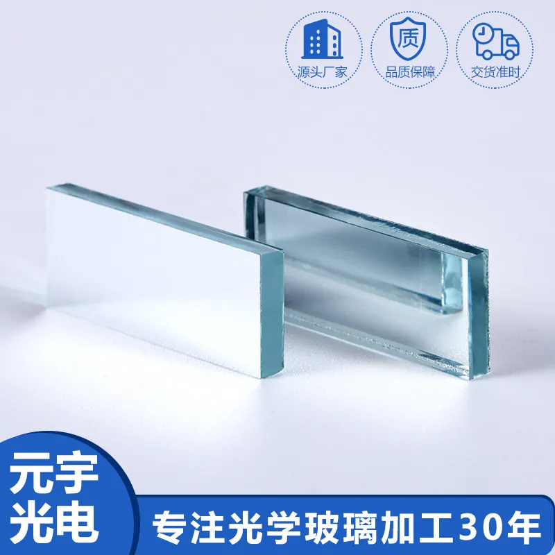
The cause is mechanical, not optical. Every thin-film layer deposited on a substrate arrives with an intrinsic stress, and that stress exerts a bending moment on the part. On a thick, small-diameter window the effect is negligible. On a large, thin mirror it can dominate the error budget.
Where the stress comes from
Two mechanisms contribute, and they behave differently.
Intrinsic stress arises during deposition as the growing film densifies. It depends on the material system, the deposition energy and the process conditions: a sputtered oxide deposited at high adatom energy typically lands in a different stress state than an evaporated layer of the same composition. Multilayer stacks are worse than single layers because stresses from individual layers add, and because a stack with alternating high- and low-index materials has alternating stress signs that create a bending moment rather than a simple uniform compression.
Thermal stress arises after deposition, from the mismatch in coefficient of thermal expansion between film and substrate as the part cools. It scales with the temperature excursion and with the CTE difference, which is why substrate choice is a coating decision as much as an optical one.
Why it scales the way it does
The deflection of a coated plate under film stress scales with the square of the diameter-to-thickness ratio. Doubling the aperture while keeping thickness constant increases deflection roughly fourfold; halving the thickness does the same. This is the single most useful fact in the whole discussion, because it explains why the problem appears suddenly in a product line rather than gradually.
A 25 mm mirror at 6 mm thick is mechanically indifferent to coating stress. A 150 mm mirror at 12 mm thick is not. The design that worked at laboratory scale does not transfer to the production aperture, and the failure looks like a process problem when it is actually a geometry problem.
The four levers
There are four practical ways to control the effect, and most successful programmes use at least two.
- Change the stress state of the coating. Deposition parameters can be tuned toward lower stress, and some designs can be re-optimised to use fewer high-stress layers. There are limits: too much relaxation and the film density, and therefore the spectral stability, degrades.
- Balance the stack. A coating designed with a compensating back-side layer, or with a symmetric stack, can cancel much of the bending moment. This costs an extra deposition step but is often cheaper than a thicker substrate.
- Increase stiffness. Thicker substrates, or larger thickness-to-diameter ratios, reduce deflection quadratically. The penalty is weight and thermal mass.
- Change the substrate material. A material with a closer CTE match to the film system reduces thermal stress; a material with higher stiffness reduces deflection for the same geometry.
What to put on the drawing
The specification that produces predictable results has three parts, and most drawings contain only the first.
1. Figure before coating and figure after coating, stated separately, with the measurement configuration named. 2. The allowed change, expressed as a power/irregularity delta rather than an absolute figure. This is the number that actually describes what the coating is permitted to do to the part. 3. The mounting assumption. A mirror held at three points behaves differently from one bonded along its edge, and differently again from one clamped. Coating stress and mounting stress are additive, and the assembly is what the system sees.
The measurement complication
Measuring figure on a coated mirror is not identical to measuring it bare. A high-reflectance coating changes the phase response on reflection, and a coating with significant reflectance at the test wavelength can make the interferometer read a different surface than the substrate beneath. Suppliers who report only a bare-substrate figure are reporting an incomplete story; buyers who compare a coated part's measurement against a bare-substrate specification are comparing two different things.
The resolution is procedural: measure at the same stage with the same instrument, report both, and agree in advance which one governs acceptance.
Why this matters more now
Apertures are growing. Laser systems, telescope designs and inspection tools all push toward larger optics, and the square-law scaling of stress deflection means the problem arrives faster than the aperture does. At the same time, thin substrates are being adopted for weight and thermal reasons, which compounds the effect.
The parts that fail are rarely badly made. They are correctly made to a specification that did not account for what the coating would do to the substrate. Fixing that is a drawing change, and it costs nothing but attention.