Specifying optical glass cold processing for automotive ADAS and LiDAR is largely a matter of deciding which three numbers actually govern the application and letting the rest follow. This guide walks through the parameters that belong on the drawing, the tolerances that genuinely change the price, and the specification items that are routinely left out and then argued about at first article.
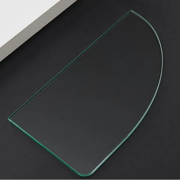
Optical Glass Cold Processing in Automotive ADAS and LiDAR
In automotive ADAS and LiDAR, that translates into a specific set of requirements rather than a general preference for quality. Automotive optics face a qualification regime unlike any consumer product: temperature swings from minus 40 to above 105 degrees Celsius, vibration, stone impact, salt spray, and a service life measured in a decade. Camera windows must stay clean enough for machine vision while resisting scratches from road grit, and LiDAR optics must survive high pulse energy at 905 or 1550 nanometers without drift.
How optical glass cold processing works in practice
Cold processing covers every shaping step that happens at room temperature: cutting the blank from a sheet, generating the outline, grinding the surface to size, lapping and polishing to optical quality, then edging, drilling, chamfering and cleaning. Unlike hot forming, no thermal cycle is applied to the part, so the substrate keeps the optical homogeneity the glass maker certified. For Automotive ADAS and LiDAR, the practical consequence is that the glass supplier's refractive index, transmission and CTE values survive manufacturing unchanged. Cold processing is normally the only route for parts that must be flat to a fraction of a wavelength, carry a functional coating, or hold a dimensional tolerance tighter than a few hundredths of a millimeter. It is also the route that scales: the same diamond tools and CNC programs that cut one prototype handle a ten-thousand-piece order, which is why most custom optics programs start with a machined sample rather than a molded one.
The tolerances that actually matter
Tolerances should be assigned per feature, not globally. Dimensional tolerances of ±0.05 mm are standard and almost free; tightening to ±0.01 mm typically adds a CNC step and a second inspection pass. Optical tolerances are a different currency: flatness is quoted in fringes (one fringe at 633 nm equals 316 nm of sag), surface quality in scratch-dig (40-20 is a normal commercial grade, 20-10 is precision), and parallelism in arcseconds. In Automotive ADAS and LiDAR, the tolerance that usually decides the price is the one nobody writes down - for example the edge chip allowance, the chamfer uniformity, or the difference in thickness across a 100 mm part. Specifying a tolerance that no fixture can hold forces the shop to sort parts instead of making them, and sorting is what turns a two-week lead time into a six-week one.
Design rules that reduce cost
A drawing that respects how glass behaves costs less and ships faster. Keep holes at least one thickness away from an edge and at least two thicknesses apart; glass does not tolerate a thin web between two holes. Replace sharp internal corners with radii of at least 0.5 mm, because a sharp corner is a crack starter. Respect the aspect ratio - a 1 mm hole in 5 mm glass is practical, a 1 mm hole in 20 mm glass is not without ultrasonic or laser drilling. Specify the chamfer rather than leaving it to the shop; an unspecified edge will be whatever the operator considers normal. For Automotive ADAS and LiDAR, also state the reference surface: which face is the optical face, which datum sets the outline, and whether a coating pattern must register to a machined feature. Half of all first-article queries trace back to an ambiguous datum rather than an impossible tolerance.
Coating and deposition considerations
Cold processing and coating are one continuous chain, and the interface between them is where most yield is lost. A polished surface must arrive at the chamber with a subsurface-damage layer thin enough that the ion-assisted deposition process can still reach a clean interface; grinding marks that survive polishing show up as scatter, and trapped polishing compound shows up as pinholes after the first warm-up cycle. Chamfers matter more than they look: a sharp edge creates a shadowed, poorly adhered zone and gives the coating a place to lift. For Automotive ADAS and LiDAR, plan the coating before the glass is cut. Coatings that run close to the substrate edge, patterns that must be registered to a machined feature, and selective-area coatings all require locating marks or a mask that has to survive the fabrication steps.
Handling, cleaning and packaging
Thin and coated glass fails in handling more often than in machining. Below roughly 0.5 mm, parts flex enough that vacuum chucks leave marks and ultrasonic energy can crack edges, so the work is carried on sacrificial plates or wax-mounted to a carrier. After coating, the surface must never touch anything: shippers use a cleanroom-compatible interleaf, edge-protecting trays and, for high-value parts, individual die-cut pockets. Cleaning follows a fixed recipe - alkaline or neutral detergent, cascaded DI rinses, IPA or nitrogen dry - because a change in rinse water quality is enough to leave mineral staining that only appears after the customer's reflow or autoclave cycle. Every handling step in Automotive ADAS and LiDAR should be specified in writing, including the packaging standard, or the same part will arrive in perfect condition once and damaged the next time.
Requirements specific to Automotive ADAS and LiDAR
In automotive ADAS and LiDAR, that translates into a specific set of requirements rather than a general preference for quality. Automotive optics face a qualification regime unlike any consumer product: temperature swings from minus 40 to above 105 degrees Celsius, vibration, stone impact, salt spray, and a service life measured in a decade. Camera windows must stay clean enough for machine vision while resisting scratches from road grit, and LiDAR optics must survive high pulse energy at 905 or 1550 nanometers without drift.
- Operating range -40 to +105 degrees Celsius
- Salt spray and abrasion resistance to automotive test standards
- Hydrophobic surface so rain and dirt shed
- Laser damage resistance at 905 or 1550 nm for LiDAR paths
IATF 16949 process documentation, AEC-Q component qualification where applicable, ISO 26262 context for the surrounding system, plus RoHS and REACH declarations.
Selection data at a glance
| Parameter | Typical capability | Notes |
|---|---|---|
| Cutting tolerance | ±0.02 mm standard, ±0.01 mm on CNC | Diamond blade or scribe-and-break |
| Thickness range | 0.05-25 mm | Below 0.3 mm needs carrier fixturing |
| Edge chamfer | 0.1 - 0.3 mm x 45 deg | Edge chips held under 0.05 mm |
| Flatness | λ/4 to λ/10 at 633 nm | Pitch polishing on fused silica |
| Parallelism | ≤ 10 arcsec | Double-side polishing |
| Surface roughness | Ra ≤ 1 nm on polished faces | Ra 0.3 nm achievable |
| Scratch-dig | 40-20 to 60-40 | MIL-PRF-13830B / ISO 10110-7 |
| Minimum hole | 0.5 mm diamond, 0.1 mm ultrasonic or laser | Aspect ratio up to 5:1 |
| Prototype lead time | 5 - 10 working days | Volume runs 15 - 25 days |
Frequently asked questions
Do you supply material certificates with the parts?
Every shipment carries the substrate lot, a dimensional report and, where relevant, a coating curve. Additional documentation such as RoHS or REACH declarations, first-article inspection reports or full traceability packages can be included when specified at quotation.
What is the fastest route from prototype to production?
Send the drawing and the application, and run the first article as a machined sample rather than a molded or cast part. Machined samples prove the tolerances and the coating at low cost, and the same CNC program then scales into volume production without a redesign.
What tolerances can cold processing realistically hold on glass?
Dimensional tolerances settle around ±0.05 mm as standard and ±0.01 mm with CNC finishing. Optical attributes are quoted separately: flatness to λ/4 or better, parallelism under 10 arcseconds, scratch-dig 40-20 commercially and 20-10 on request. The practical limit is set by how much you are willing to inspect, not by the machine.
Need a quotation for optical glass cold processing?
Send your drawing, target specification or coating requirement and an optical engineer will reply within 24 hours with a price and a lead time.
Request a Quote Email an engineer