There is always more than one way to solve the optical problem in scientific and laboratory instrumentation, and the options are not equally good at everything. This article compares optical glass cold processing against the materials, processes and design approaches it competes with, on the criteria that matter commercially: performance, durability, unit cost and lead time.
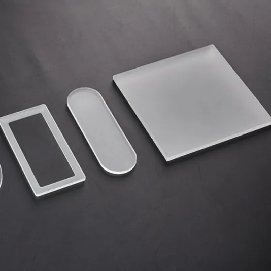
Optical Glass Cold Processing in Scientific and Laboratory Instrumentation
In scientific and laboratory instrumentation, that translates into a specific set of requirements rather than a general preference for quality. Laboratory instruments are judged on reproducibility, so their optics must be documented and their performance must not drift between measurement campaigns. Many instruments are calibrated against a reference path, which means a small change in a window or filter shifts every reading rather than producing an obvious failure.
Substrate and material selection
Material choice drives nearly every downstream decision. Soda-lime and B270 are cheap and polish quickly, so they suit cover glass and lighting filters where surface quality matters more than index control. Borosilicate 3.3 and Eagle XG bring low thermal expansion, which keeps flatness stable through the coating chamber and through soldering in Scientific and Laboratory Instrumentation. Fused silica and quartz are chosen when UV transmission, high laser damage threshold or thermal shock resistance is specified; they cost three to eight times more and grind more slowly because of their hardness. Sapphire is the extreme case - nearly scratch-proof and thermally conductive, but it must be machined with diamond tooling and its anisotropy makes polishing direction-sensitive. State the material grade, not just the family: BK7 and B270 are not interchangeable, and a substrate substitution can move a filter's center wavelength by several nanometers.
What drives cost and lead time
Cost in cold processing is driven by three things: how much material has to be removed, how tight the tolerance is, and how many parts share the setup. Material dominates for sapphire, quartz and large blanks. Tolerance dominates whenever it forces a finishing operation - going from 60-40 to 20-10 scratch-dig roughly doubles polishing labor, and single-point diamond turning is a different cost class entirely. Batch size decides amortisation: a fixture that costs a few hundred dollars is irrelevant across 5,000 parts and decisive across five. The cheapest article to buy is almost never the cheapest to own, though. In Scientific and Laboratory Instrumentation, a part that arrives with a consistent edge and a documented coating curve removes an incoming-inspection station, and that saving usually exceeds the price difference between two quotations.
The tolerances that actually matter
Tolerances should be assigned per feature, not globally. Dimensional tolerances of ±0.05 mm are standard and almost free; tightening to ±0.01 mm typically adds a CNC step and a second inspection pass. Optical tolerances are a different currency: flatness is quoted in fringes (one fringe at 633 nm equals 316 nm of sag), surface quality in scratch-dig (40-20 is a normal commercial grade, 20-10 is precision), and parallelism in arcseconds. In Scientific and Laboratory Instrumentation, the tolerance that usually decides the price is the one nobody writes down - for example the edge chip allowance, the chamfer uniformity, or the difference in thickness across a 100 mm part. Specifying a tolerance that no fixture can hold forces the shop to sort parts instead of making them, and sorting is what turns a two-week lead time into a six-week one.
How it compares with the alternatives
Cold processing competes with three alternatives, and picking the wrong one is expensive. Hot pressing or molding produces aspheres and free-form shapes cheaply at volume, but leaves tool marks that need polishing and cannot hold interferometric flatness without it. Laser cutting and laser ablation skip the tooling and handle complex outlines and holes well, but leave a heat-affected edge and rarely hold tight surface quality on the cut face. Waterjet cutting is fast and thickness-agnostic but leaves a frosted edge that always needs finishing. For most flat optics with a coating and a defined surface figure - the majority of the parts used in Scientific and Laboratory Instrumentation - conventional cold processing with CNC finishing remains the only route that delivers all three attributes at once: dimensional accuracy, optical surface quality and a coating-ready surface.
Requirements specific to Scientific and Laboratory Instrumentation
In scientific and laboratory instrumentation, that translates into a specific set of requirements rather than a general preference for quality. Laboratory instruments are judged on reproducibility, so their optics must be documented and their performance must not drift between measurement campaigns. Many instruments are calibrated against a reference path, which means a small change in a window or filter shifts every reading rather than producing an obvious failure.
- Documented and stable transmission curves
- Batch-to-batch consistency for calibration validity
- Chemical resistance to laboratory solvents
- Precision surface quality for interferometric paths
ISO/IEC 17025 context for testing laboratories, ISO 10110 drawings, and full material and coating documentation.
Selection data at a glance
| Parameter | Typical capability | Notes |
|---|---|---|
| Cutting tolerance | ±0.02 mm standard, ±0.01 mm on CNC | Diamond blade or scribe-and-break |
| Thickness range | 0.05-25 mm | Below 0.3 mm needs carrier fixturing |
| Edge chamfer | 0.1 - 0.3 mm x 45 deg | Edge chips held under 0.05 mm |
| Flatness | λ/4 to λ/10 at 633 nm | Pitch polishing on fused silica |
| Parallelism | ≤ 10 arcsec | Double-side polishing |
| Surface roughness | Ra ≤ 1 nm on polished faces | Ra 0.3 nm achievable |
| Scratch-dig | 40-20 to 60-40 | MIL-PRF-13830B / ISO 10110-7 |
| Minimum hole | 0.5 mm diamond, 0.1 mm ultrasonic or laser | Aspect ratio up to 5:1 |
| Prototype lead time | 5 - 10 working days | Volume runs 15 - 25 days |
Frequently asked questions
How thin can you go before handling becomes the problem?
Around 0.5 mm parts stop behaving like rigid bodies. Below that we mount them on carriers or sacrificial plates, which adds cost but prevents the flexing, chipping and edge damage that otherwise dominate yield.
Do you supply material certificates with the parts?
Every shipment carries the substrate lot, a dimensional report and, where relevant, a coating curve. Additional documentation such as RoHS or REACH declarations, first-article inspection reports or full traceability packages can be included when specified at quotation.
What is the fastest route from prototype to production?
Send the drawing and the application, and run the first article as a machined sample rather than a molded or cast part. Machined samples prove the tolerances and the coating at low cost, and the same CNC program then scales into volume production without a redesign.
Need a quotation for optical glass cold processing?
Send your drawing, target specification or coating requirement and an optical engineer will reply within 24 hours with a price and a lead time.
Request a Quote Email an engineer