Optical fiber and cable manufacturing depends on a set of quiet, precision glass parts: polished ferrules and sleeves, collimating and focusing substrates, glass spacers inside connectors, and the fixtures that hold fiber during termination. None of them are glamorous, but each one's flatness, edge quality and surface finish decide insertion loss and, more quietly, production yield on the line. This guide sets out the numbers that belong on the drawing, the tolerances that genuinely move cost, and the items routinely left off until first article.
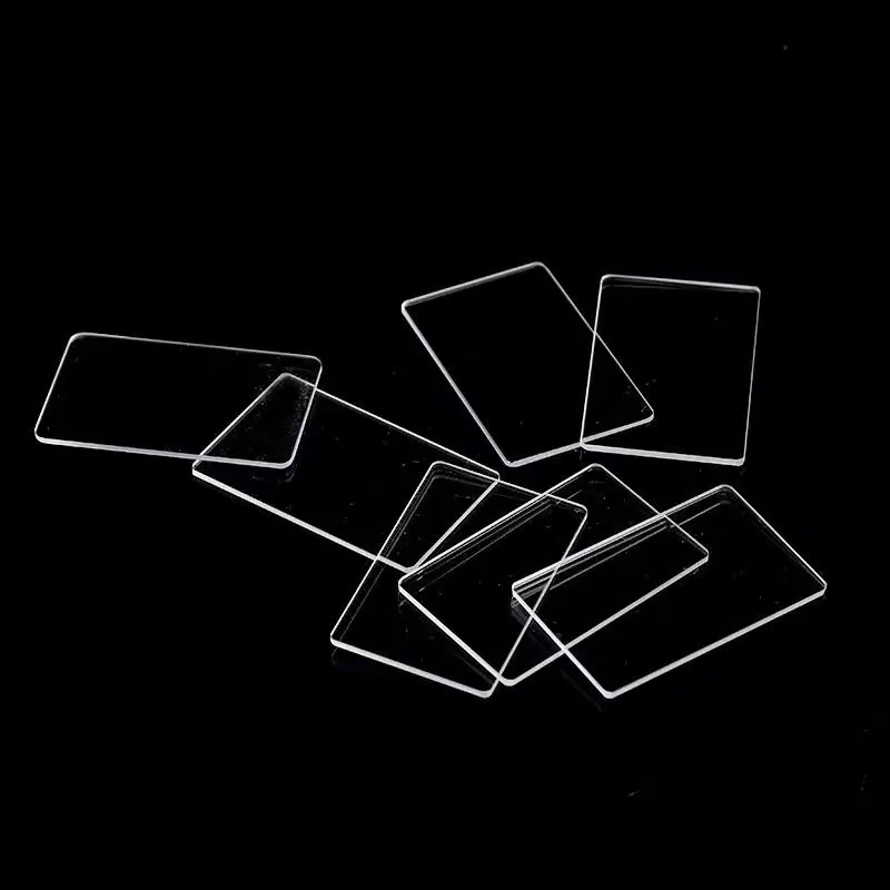
Optical Glass Cold Processing in Optical Fiber and Cable Manufacturing
A connector ferrule end face, a glass spacer that sets the air gap in a collimator, or a substrate that a lens is bonded to are all cold-processed: shaped, ground and polished without changing the glass bulk. In cable manufacturing the same discipline appears in termination fixtures and in the glass strength members that protect the fiber path. The optical function is usually simple - present a flat, clean, well-angled surface to the beam - but the mechanical precision required to do that at line rate is not. The specification is therefore less about exotic optics and more about repeatable geometry: flatness, wedge, edge break and surface finish held across thousands of parts.
Design rules that reduce cost
Hold the tolerance only where the beam actually cares. A spacer that sets a collimator gap wants tight thickness and parallelism; a cover substrate that merely protects a bond wants neither. Specify the largest edge break the process can hold rather than the smallest, because sharp edges chip in handling and cost yield. Prefer standard thicknesses and diameters so the blank can be cut from stock rather than block-sawn to size. Where a part is polished on one face only, say so - double-sided polishing is a different operation and a different price. Coat or mark only the faces that need it, and avoid calling for a cosmetic surface finish that the optical path never sees.
Coating and deposition considerations
Most fiber-manufacturing glass parts are uncoated, but a few carry a thin film: an anti-reflective layer on a polished window in the path, or a marker or alignment layer on a fixture. When a coating is present, state which face carries it and what it must survive - wiping during termination, solvents used in cleaning, or the curing heat of an adhesive. A coating centred on the wrong wavelength or applied to the wrong face is a re-run, not a tweak. For AR on a path window, specify the band the system uses (often 1310 and 1550 nm for telecom) so the layer is tuned to the actual signal rather than to a generic visible value.
How optical glass cold processing works in practice
Cold processing starts from a blank that is cut, then ground to rough geometry, then polished to the final surface. The flatness and surface finish come from the polish, while wedge and thickness come from how the part is held and measured during grinding. Edge break is added in a final chamfer or tumble step. The practical limit on yield is rarely the machine; it is contamination and handling - a single grain of abrasive carried from the grind station to the polish station scatters the surface. That is why line rate and part count, not just tolerance, drive the process choice between batch polishing and single-part fixturing.
The tolerances that actually matter
For a ferrule or collimator spacer the governing numbers are thickness (which sets optical spacing), parallelism or wedge (which sets beam angle), and the end-face flatness and surface finish (which set loss and back-reflection). For a protective substrate, surface form matters less than a clean, chip-free edge. A surface finish specified in scratch-dig terms should be chosen against the actual scatter budget, not a habitually fine number, because each step finer multiplies cost. Wedge is the tolerance most often under-specified: two arcminutes versus ten changes the fixturing and the inspection, and shows up as angle error in the field rather than as a cosmetic defect.
Handling, cleaning and packaging
Glass parts for fiber manufacturing are small, edged and easily chipped, so handling is part of the specification. Call for edge-protective packaging and for a cleaning state that matches the next process: a termination fixture may need a solvent-cleaned, particle-free surface, while a bare spacer may only need to be free of grinding residue. State whether the part is delivered loose or in a fixture-ready carrier, because that decides how much re-handling the line absorbs. Where the part enters an automated termination machine, a defined orientation and a clean, dry, static-safe pack reduces scrap more than a tighter polish does.
Requirements specific to Optical Fiber and Cable Manufacturing
Cable and connector manufacturing is a volume, line-rate world, so the specification has to survive the line, not just the lab. The decisive requirements are repeatable geometry across large batches, chip-free edges that do not fail during automated handling, and a cleaning and packaging state matched to the next process. Tolerances should be set against the insertion-loss and back-reflection budget of the actual connector or collimator, and confirmed against the current assembly drawing rather than a generic optics spec, because a change in fiber or adhesive shifts what the glass part must hold.
- Hold tight tolerance only on thickness, parallelism and the optical end face
- Specify the largest edge break the process allows to protect yield
- For AR windows, tune the coating to the system band (often 1310/1550 nm)
- Package and clean the part for the next automated process, not just for shipping
Framework references: surface quality and element tolerances follow ISO 10110; connector geometry references the relevant IEC or industry interface standard. Coating wavelengths are set by the fiber system design; confirm against the current assembly specification rather than a generic value.
Selection data at a glance
| Parameter | Typical capability | Notes |
|---|---|---|
| Thickness / spacing | tight, per collimator or connector design | Sets optical gap |
| Wedge / parallelism | 2 arcmin achievable, 10 typical | Beam-angle control |
| End-face flatness | per loss budget | Affects insertion loss |
| Surface finish | scratch-dig per scatter budget | Avoid habitually fine |
| Edge break | largest process-safe radius | Protects yield |
| AR coating (if used) | tuned to 1310/1550 nm | State coated face |
Frequently asked questions
Which tolerance matters most on a ferrule or spacer?
Thickness and parallelism, because they set the optical spacing and the beam angle. Surface finish matters for loss and back-reflection, but wedge is the one most often under-specified and it shows up as angle error in the field.
Should I ask for the finest possible surface finish?
Only if the scatter budget needs it. Each finer scratch-dig step multiplies cost, and most protective or fixture parts never see the beam closely enough to justify it. Tie the finish to the actual loss budget.
Does an AR coating help on these parts?
Only on a path window, and only if tuned to the system band - commonly 1310 and 1550 nm for telecom. State which face carries it and what cleaning or adhesive heat it must survive, or it becomes a re-run.
Need a quotation for optical glass cold processing?
Send your drawing, target specification or coating requirement and an optical engineer will reply within 24 hours with a price and a lead time.
Request a Quote Email an engineer