An earth observation instrument is a radiometer that happens to fly. Its most consequential optical parts are band filters, and their job is not to make an image look right but to define what a digital number means. That makes traceability, angular behaviour and stability a data question rather than a cosmetic one, because a filter that shifts, leaks or loses transmission converts into a bias in the science product that is very hard to correct after launch. This note covers what has to be inspected, what has to be recorded, and where the conventional camera-grade filter specification falls short.
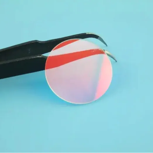
IR Filters in Satellite and Earth Observation Instruments
Earth observation instruments divide roughly into three optical needs. Reflected-solar instruments use band filters that define channels across the visible, near-infrared and short-wave infrared for surface reflectance and vegetation or water monitoring. Thermal-infrared instruments use longer-wavelength channels where the measurement is the emission of the scene itself, and the filter chain there is a cold-optics problem as much as a spectral one. And limb or atmospheric sounding instruments use narrow filters where out-of-band rejection is the whole task. Across all three, the filter sits in front of a detector that is calibrated against a reference, so its own transmission, angular behaviour and drift enter the calibration chain. A terrestrial camera filter is specified for how an image looks; a space filter is specified for what a pixel value represents, and it is reviewed by people who will correct the data years later for a filter they cannot touch.
Inspection and measurement
The measurement that matters most is the spectral characterisation of the actual part, not of the coating design. A spectrophotometer trace covering the passband edges, the stop-band rejection and, critically, the transition region where the band edge sits inside real scene radiance, is the core record. Beyond the curve, four further measurements earn their place. Angular performance, because a bandpass filter's passband shifts with incidence and a wide-field or scanned instrument sees a cone wide enough that the on-axis trace alone is not representative. Transmission loss and figure, since a filter with low loss still degrades a low-radiance channel's signal-to-noise. And edge quality, because for a filter mounted by an edge in a cold frame, the edge is both the mounting surface and the stress concentrator that can shift the curve. Every one of these should be measured on the part that will fly, not on a witness coupon, and recorded against the part's own serial number.
Standards, documentation and traceability
Three documentation habits keep a filter programme defensible. First, tie the measurement to the part: spectral curve, angular data, substrate and coating identity, thickness and coating thickness, all under one serial number that follows the part through integration. Second, state which standard each measured quantity is expressed in, and quote the current official text for it, because the standards that govern optical drawing, coating durability, space-qualified materials and outgassing are all revised and a specification that cites a superseded issue is a specification nobody can adjudicate. Third, separate the acceptance criteria from the design intent, and record what was accepted, not only what was required. Where a supplier asserts compliance with a material or process standard, the declaration should name the standard, the issue, and the scope, and any RoHS or REACH statement should cover the actual substrate and coating stack rather than the generic word glass. The practical test is whether a later analyst, given only the delivered documentation, could reconstruct why a pixel has the value it has.
Common failure modes and how they show up
Four failures are characteristic. Spectral shift, where a coating with internal stress changes its optical thickness over time or temperature and the band edge walks, which is a calibration error that looks like a slowly drifting scene. Edge-leak, where the mount does not seal the substrate perimeter and light from outside the intended band enters the channel, producing a background that calibration cannot distinguish from signal. Outgassing and contamination, where organic residue in the coating or in the mount releases in vacuum and deposits on the optic, and where handling before or after integration leaves particulate that scatters directly into the detector. And coating delamination or crazing, usually initiated by a thermal cycle or by handling in a cold state, which appears as a spreading haze. The first two are invisible in an image and only a spectral re-check will find them, which is exactly why the periodic re-measurement record is part of the programme rather than a formality.
Handling, cleaning and packaging
Space optics are assembled in a clean environment and then never cleaned again, so the handling regime has to be designed in. Filters are edge-mounted, so they are handled at the edge by definition, and the damage that matters is a chip or a stress riser at exactly the place that holds it. Specify the mounting interface and the permitted handling method, and require that no cleaning step is applied after coating without written confirmation that the coating tolerates it. Packaging should be the part's own sealed environment: an individual container, a cleanliness level, and a documented inspection before and after packing. For filters that will be integrated far from their supplier, keep the data that would allow a re-measurement after integration, and decide in advance who re-checks the spectrum once the instrument is integrated and again after any thermal vacuum cycle, because that is where a shift would first become measurable.
The tolerances that actually matter
The tolerances that dominate a space filter specification are angular and thermal rather than dimensional. Angular tolerance means the passband must hold across the full field or scan angle, including any shift of the band edge and any change in out-of-band rejection at the edge of the cone; this is where many otherwise adequate camera filters fail, because they were specified on axis. Thermal tolerance means the band edge must remain within a stated interval across the operating range of the instrument and, in a thermally controlled cold optics box, that the filter sits close enough to the detector assembly to inherit its stability. Out-of-band rejection is usually the largest numeric requirement and the one most often written without a bandwidth, which makes it unenforceable. Then come the conventional items: substrate thickness uniformity, wedge if the element is used in a collimated path, figure and surface quality for the transmitted beam, and the coating thickness uniformity across the clear aperture. Where the requirement is a flat-top passband rather than a simple peak, that has to be stated as a specification and measured accordingly, since a nominal bandwidth says nothing about flatness across the band.
Requirements specific to Satellite and Earth Observation Instruments
Space and earth observation instruments require a filter to be specified as a radiometric element: passband shape, out-of-band rejection with its bandwidth defined, angular performance across the full field or scan cone, and stability across the operating temperature range, all measured on the part that will fly. Require a spectral trace under serial-number traceability, with substrate, coating and thickness identified, and keep a witness coupon where the programme permits so a re-check is possible without the flight part. Outgassing and contamination control should be declared against the current official space materials and process requirements, and any restricted-material statement should cover the actual substrate and coating stack. Agree in advance who re-measures the spectrum after integration and after thermal vacuum cycling, since a shift there cannot be corrected after launch.
- Passband shape, out-of-band rejection bandwidth and flat-top requirement stated as measured data
- Spectral performance specified across the full field or scan cone, not on axis only
- Band edge stability stated as an interval across the operating temperature range
- Measurements made on the flight part under serial-number traceability
- Witness coupon retained and re-measurement after integration and thermal vacuum cycling agreed in advance
Framework references: ISO 10110 for surface figure, surface quality and wedge on finished parts. Space-qualified material and process requirements, outgassing limits, and restricted-material or export-control rules are programme and jurisdiction specific and must be taken from the current official texts, along with the applicable optical coating and durability standards in their current issue. Declarations of conformity are the supplier's to make for the actual material and coating stack.
Selection data at a glance
| Parameter | Typical value | Notes |
|---|---|---|
| Passband | Stated shape and flatness | Radiometric |
| Out-of-band rejection | With bandwidth defined | Enforceable |
| Angular range | Across field or scan cone | Not on-axis only |
| Thermal stability | Edge shift interval | Operating range |
| Outgassing | Per current space requirement | Vacuum |
| Traceability | Serial number plus witness | Re-checkable |
Frequently asked questions
Why can't we just use a camera-grade bandpass filter?
You can, and for a prototype it is often the sensible move. What a camera-grade filter does not carry is the angular performance across a wide field, the thermal stability of the band edge, and the documentation that lets someone later reconstruct why a pixel has the value it has. Those three become mandatory once the measurement has to remain defensible.
How much out-of-band rejection is enough?
Enough that leakage from a bright out-of-band source stays below the noise level of the weakest channel you intend to use, which depends on scene radiance and detector characteristics rather than on a rule of thumb. Specify the rejection with its bandwidth and the measurement bandwidth, otherwise the number is not testable.
Can a filter be re-measured after integration?
It can be re-measured, but only if it was characterized before integration and if the integration did not coat the mount aperture or change the element's angular condition. Decide the re-check points before integration, and keep a witness coupon where the programme permits, since the flight part itself may not be recoverable.
Need a quotation for ir filters?
Send your drawing, target specification or coating requirement and an optical engineer will reply within 24 hours with a price and a lead time.
Request a Quote Email an engineer