Ring-laser gyros and fiber-optic gyros, and the cavity mirrors and beam splitters inside them, hold their measurement in an optical path held to arc-second and parts-per-million levels, so the glass parts that define that path must be cold-processed to a stability most camera optics never need. The specification is really about dimensional and thermal stability that keep the bias where it was calibrated. This guide sets out the numbers that belong on the drawing for gyro and inertial-sensor optics.
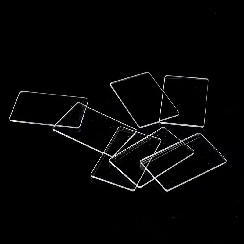
Optical Glass Cold Processing in Optical Gyroscopes and Inertial Sensors
A ring-laser gyro traps a standing wave in a cavity whose mirrors define the path length, and a fiber-optic gyro winds that path in fiber but still uses precision beamsplitters and collimators at the ends. The glass parts set the geometry the bias depends on, so a few arcseconds of wedge or a fraction of a wave of surface form is not a cosmetic detail but a measurement error. Cold processing here means grinding and polishing the substrate to that figure, edge and centreering it, stress-relieving it, and finishing it clean, because the part's job is to hold dimension and polarization through temperature and time rather than to form an image a viewer likes.
Design rules that reduce cost
Symmetric designs cost less than asymmetric ones, because a part that can be processed from both faces in one setup holds figure more easily. Relax the tolerances that do not move bias, such as cosmetic scratch-dig on a non-critical face, and hold tight only the numbers that do, such as cavity-mirror flatness and parallelism. Batch processing identical parts spreads the first-article cost, and a standard substrate avoids a special melt. The saving is in putting the tight numbers where they change the measurement and leaving the rest at commercial grade, rather than specifying everything to the same extreme.
Coating and deposition considerations
The mirrors and beamsplitters carry low-stress dielectric stacks, because coating stress induces birefringence that twists the polarization and shifts the bias. The deposition is qualified for environmental stability, not just for reflectance, and the stress is measured rather than assumed. Where a part sits in the cavity, both faces may carry functional layers, and the coating is designed so its own thermal shift does not fight the substrate's. State on the drawing which face carries each layer, and require a stress report at first article, because a stressed coating is the quiet way a gyro drifts out of its calibrated band.
How optical glass cold processing works in practice
The substrate is ground to near-figure, polished to the required peak-to-valley, and edge-finished so it seats without chipping. For a cavity mirror, flatness and parallelism are the critical pair: flatness sets the wavefront, parallelism sets the path length and the mode, and both are checked interferometrically. A stress-relief step between rough and fine processing removes the figure error that grinding locks in, because polishing alone will not remove subsurface damage that later relaxes. The part leaves the process clean and measured, with the as-figured values recorded against the lot rather than against a target alone.
The tolerances that actually matter
Flatness and parallelism, usually stated in waves and arc-seconds, dominate because they act directly on the path. Surface form peak-to-valley sets the wavefront quality, and scratch-dig matters where a defect scatters light into the wrong mode. Coating uniformity keeps the reflectance where designed, and thermal-expansion match to the spacer or housing keeps the path length steady across temperature. Stress birefringence from the coating or mount is the number that ties optical and mechanical specs together, because it is what actually moves the bias. These are the values written on the drawing, with the rest left at commercial grade.
Handling, cleaning and packaging
Gyro optics are handled in a clean environment and kept particle-free, because a contaminant on a cavity mirror scatters light into the wrong mode and shifts the reading. Edges are chamfered and protected so a knock does not start a crack at the rim, and the part is packed so the optical face never touches a surface, with the orientation marked where the coating is face-specific. The handling discipline is part of the lot record, because a part that arrives clean but is wiped with the wrong cloth can fail the figure it was qualified for, and reaching it inside an assembled inertial unit is expensive.
Requirements specific to Optical Gyroscopes and Inertial Sensors
The duty is dimensional and thermal stability that holds the bias, so every number on the drawing serves that. Flatness and parallelism are specified to arc-second and parts-per-million levels, surface form to a tight peak-to-valley, and the coating is specified for low stress because birefringence is what actually moves the reading. The substrate's thermal expansion is matched to its spacer and housing so the path length holds across temperature, and the part is cleaned, handled and traced as a lot with a first-article record covering figure, parallelism and coating stress. Bias stability, not image quality, is the specification.
- Flatness and parallelism (wedge) per cavity specification
- Low stress-induced birefringence from coating and mount
- Surface form PV and scratch-dig per ISO 10110
- Thermal-expansion match and lot traceability
Framework references: surface form and flatness per ISO 10110-5, scratch-dig per ISO 10110-7, and a first-article and lot certificate covering figure, parallelism and coating stress. Bias-stability requirements follow the inertial-system specification; confirm against the current official text rather than a single value.
Selection data at a glance
| Parameter | Typical capability | Notes |
|---|---|---|
| Flatness | lambda/10 to lambda/20 typical | Cavity mirror |
| Parallelism | arcsec grade | Path length |
| Surface form | PV 0.1 um | Per ISO 10110-5 |
| Scratch-dig | 20-10 typical | Per ISO 10110-7 |
| Substrate | fused silica, borosilicate | Per CTE match |
| Coating | low-stress dielectric | Bias stable |
| Traceability | batch ID, cert | Lot record |
Frequently asked questions
Why does stress birefringence matter in a gyro?
A stressed coating or mount twists the polarization and shifts the gyro bias, and the optical path is held to arc-second and ppm levels, so low-stress dielectric stacks and stress-relieved substrates are specified explicitly. The stress report at first article is what catches it before the part enters an assembled unit.
What tolerances actually move bias?
Flatness, parallelism (wedge) and surface form of the cavity mirrors dominate. A few arcseconds of wedge or a fraction of a wave of form reads directly as bias error, which is why those numbers are tighter than for a camera lens and why they sit at the top of the drawing.
Does thermal expansion matter?
Yes. The cavity must hold dimension across temperature, and a CTE mismatch to the spacer or housing drifts the path and the bias. The substrate and its mates are specified together for thermal stability, because the bias is a function of path length, not just of surface quality.
Need a quotation for optical glass cold processing?
Send your drawing, target specification or coating requirement and an optical engineer will reply within 24 hours with a price and a lead time.
Request a Quote Email an engineer