Failures in coated color filter glass used in solar and photovoltaic manufacturing tend to follow a small number of patterns, and each pattern has a signature. This article walks through the common failure modes, how to tell them apart with measurements rather than guesswork, and the process or design changes that actually remove the root cause.
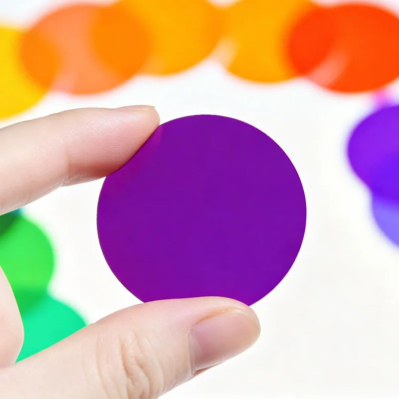
Coated Color Filters in Solar and Photovoltaic Manufacturing
In solar and photovoltaic manufacturing, that translates into a specific set of requirements rather than a general preference for quality. Solar manufacturing combines very large glass areas with aggressive cost targets and 25-year outdoor exposure. Coatings are used to raise transmission and reduce soiling, while glass is used as tooling and protection in the production equipment itself. Durability under ultraviolet, humidity and thermal cycling is the entry ticket.
Design rules that reduce cost
Designing with coated color filters is mostly about angle, heat and mounting. Decide the acceptance cone first: a narrow cone buys a steeper edge and purer color, a wide cone buys luminous efficiency at the cost of color saturation. Then decide how the part is retained - a ring, clips, adhesive or a frame - and leave a margin of at least 1 mm that carries no coating so the retention never touches an optical surface. Keep patterned areas at least 0.3 mm from the edge for the same reason. If the part sits behind a condenser or a lens, model the angular spread rather than assuming collimated light, because the effective spectrum will be a weighted average over that spread. For Solar and Photovoltaic Manufacturing, a short note on the drawing stating the acceptance angle, the mounting method and the maximum flux prevents most of the arguments that otherwise surface at first article.
Common failure modes and how they show up
The classic field failures are color shift with age, delamination at the edge, and cracking from thermal shock. Color shift almost always traces to moisture uptake in a coating deposited without ion assistance, or to a design that assumed a lower operating temperature than the application delivers. Delamination starts at a chamfer or an uncoated edge and spreads inward, and it is accelerated by any cleaning solvent that reaches the interface. Thermal shock cracks appear when the center of the plate and its mounting ring heat at different rates, which is a design problem rather than a coating problem. In Solar and Photovoltaic Manufacturing, the fastest way to prevent all three is to specify the maximum flux, the mounting method and the cleaning chemicals at the quotation stage, then let the coating design be built around those three numbers instead of discovering them in the field.
Inspection and measurement
Every color filter should ship with a measured curve, not a nominal one. Spectrophotometry from 350 to 1050 nm at the specified angle of incidence is the baseline; for parts used in laser or high-flux systems, laser damage threshold data and a transmission map across the aperture are worth requesting. Color coordinates, where the customer specifies them, need a defined illuminant and observer, and they must be measured on the actual part rather than predicted from the design. In Solar and Photovoltaic Manufacturing, the incoming inspection that catches the most escapes is a physical check of the patterned areas and the edge quality, because a coating can be spectrally perfect and still be rejected for a chip or a registration error that a bench measurement never sees.
Coating and deposition considerations
The coating design is where the color is actually made. Interference stacks are built from alternating layers of materials such as Nb2O5, Ta2O5 or TiO2 against SiO2, and the layer count and thickness ratio tune the reflection band, the transition steepness and the ripple in the passband. IAD or another ion-assisted process is preferred because it produces dense, hard oxide layers with little moisture shift, so the color does not move when humidity changes. Because the shift with angle is intrinsic, multi-zone filters are designed so that each zone has its own stack and its own angular window. For Solar and Photovoltaic Manufacturing, decide early whether the part needs a hard coat on both faces (scratch resistance and second-surface reflection control) or a single coated face, and whether any area must remain uncoated for a sensor or a bond line.
Requirements specific to Solar and Photovoltaic Manufacturing
In solar and photovoltaic manufacturing, that translates into a specific set of requirements rather than a general preference for quality. Solar manufacturing combines very large glass areas with aggressive cost targets and 25-year outdoor exposure. Coatings are used to raise transmission and reduce soiling, while glass is used as tooling and protection in the production equipment itself. Durability under ultraviolet, humidity and thermal cycling is the entry ticket.
- Twenty-five year UV and humidity stability
- Very large coated areas with uniform performance
- Hydrophobic or easy-clean surface behavior
- Cost per square meter under pressure
IEC 61215 and IEC 61730 context for module durability, plus RoHS and REACH declarations for the coated glass.
Selection data at a glance
| Parameter | Typical value | Notes |
|---|---|---|
| Dominant wavelength | 450-660 nm, custom to ±5 nm | Per color chip |
| Transmission in band | >= 85 % (T>= 90 % on tuned designs) | At normal incidence |
| Out-of-band blocking | OD2 - OD4 | Visible to NIR |
| Coating type | IAD multilayer hard oxide | Color-by-interference |
| Substrate | B270, borosilicate, ultra-clear, quartz | Heat-resistant grades for high flux |
| Thickness | 0.3-3 mm | 1.1 mm typical for gobos |
| Size tolerance | ±0.1 mm, ±0.05 mm on request | Round, square, custom outline |
| Pattern tolerance | ±0.05 mm registration | Screen print, lithography or mask |
| Operating temperature | up to 400 °C substrate dependent | Thermal shock is the real limit |
Frequently asked questions
Can you print a logo or pattern in a specific color?
Yes. Patterns are produced by masking or lithography before coating, or by screen printing a patterned layer, with registration typically held to ±0.05 mm. Keep features at least 0.3 mm from the edge and provide artwork as vector data.
Will the color fade over time?
No. Interference coatings are inorganic hard oxide layers; there is no dye to bleach. Color changes in the field almost always come from a humid coating deposited without ion assistance, or from a design that was specified for a lower operating temperature than the application reached.
What substrate should I use for a high-power lighting fixture?
Borosilicate or a dedicated heat-resistant glass for most fixtures, and fused silica or a low-expansion substrate when the part experiences rapid thermal cycling. Thin substrates survive thermal shock better than thick ones because the gradient across the plate is smaller.
Need a quotation for coated color filters?
Send your drawing, target specification or coating requirement and an optical engineer will reply within 24 hours with a price and a lead time.
Request a Quote Email an engineer