A tablet or capsule sorting machine makes an accept or reject decision from colour, often at high rate with a modest difference between a good product and a slightly discoloured one. The filter in front of the sensor is what turns that small difference into a reliable signal, and it is also the part most often left unspecified until the machine starts rejecting good product. This guide works through what to write on the specification for a pharmaceutical sorting application.
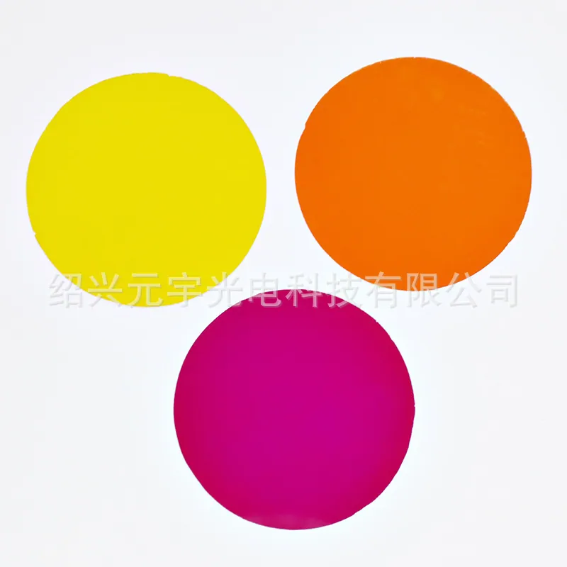
Coated Color Filters in Pharmaceutical Tablet and Capsule Inspection
Pharmaceutical sorting looks at individual units passing a fast line, and the decision is frequently a colour one: an incorrect shade, a printed mark that has shifted or faded, a coating that has bled, or a capsule whose two halves do not match. The camera sees the unit under a fixed illumination and passes judgement on the resulting colour signal, so anything that changes the spectral response between two passes through the machine becomes a source of false rejection. A coated colour filter in front of the sensor narrows what the camera measures to the band that actually discriminates the defect, and it does so before the signal reaches the sensor, which is more stable than processing a full colour image afterwards. The filter therefore has to be thought of as part of the measurement chain whose behaviour changes over the life of the machine, not as a consumable accessory.
The tolerances that actually matter
Three figures carry the specification. The first is the pass band position, which must be stated against the illumination the sorting line uses and the colour space the decision logic works in, not as a generic wavelength number. The second is the colour consistency between production lots, because a filter that shifts between lots shifts the measured colour of every unit and shows up as the machine quietly changing its reject rate. The third is the uniformity of the band across the aperture, since a sorting camera looks at units across a wide field and a band that sits differently at the edge than in the centre produces a systematic difference in how units are judged near the edge of the field. Surface quality and dimensional tolerance are conventionally expressed under the optical drawing standard, so those values should be taken from the current issue rather than a catalogue.
Design rules that reduce cost
Cost in this application is dominated by the filter's size and by the sharpness of its band. A standard catalogue coloured glass with a hard top layer is usually sufficient for a sorting line and is considerably cheaper than a custom deposited stack, and a narrower band is not automatically better because a too-narrow band can drop the transmitted signal to a level where the camera's noise becomes the limit. Keeping the aperture small and standard reduces both the material yield loss and the coating time, and a simpler flat plate is cheaper than a polished wedge unless the geometry genuinely requires an angular correction. Standardising one filter design across the sorting machines of a line is usually a bigger saving than optimising the band further, because it removes the per-machine re-qualification that a bespoke band would demand.
Coating and deposition considerations
A deposited layer on top of a coloured substrate sharpens the band edge and deepens the blocking outside it, which is exactly what a sorting application wants, but it introduces three practical constraints. The stack must be uniform across the aperture, since a graded deposition shows as a field-edge effect on the product. The layers must be hard enough to survive the cleaning the machine allows, because a sorting line is cleaned to a standard that a laboratory coating would not be expected to meet. And the whole stack must be characterised for its shift with angle, because a sorting camera at speed works well off normal incidence and a band defined only on axis will drift as the unit passes. The right approach is to agree the stack with the coating supplier against the illumination and the incidence range of the machine rather than to select a stock coating.
How coated color filter glass works in practice
In the machine, the filter is a flat plate held in front of the sensor or in front of the illumination path, and its job is to make the ratio between the two consistent enough that a small colour change in the unit produces a usable change in signal. Colourless coloured substrates work by bulk absorption, so their band position depends on thickness, which means the thickness has to be held and stated alongside the composition. Deposited layers work by interference, so their band position depends on layer thickness and deposition conditions, which means lot-to-lot control comes from the coating process rather than from the glass. In practice a hybrid is common: a bulk-absorbing substrate to remove the out-of-band light and a thin-film layer to sharpen the edge the decision logic actually uses. Reads that way round, the specification becomes a question of how much of the separation is wanted from the glass and how much from the coating.
Requirements specific to Pharmaceutical Tablet and Capsule Inspection
Specify the pass band against the line illumination and the decision colour space, and hold lot-to-lot colour consistency as a formal requirement rather than assuming it. Textured uniformity across the aperture matters because the field edge is judged the same as the field centre, and the stack must be characterised across the incidence range the units actually present. Confirm the cleaning compatibility of the coating with the machine's approved method, keep the aperture standard, and hold one qualified reference filter against which the reject rate is checked.
- Pass band stated against line illumination and decision colour space
- Lot-to-lot colour consistency written in as a requirement
- Band uniformity across the aperture, not just on axis
- Stack characterised across the real incidence range
- Coating cleaning compatibility confirmed against the machine method
- One qualified reference filter held for reject-rate comparison
Framework references: pass band, blocking, surface quality and dimensional tolerances for optical filters are conventionally stated in ISO 10110 and the relevant filter standard for the wavelength region in use; confirm values in the current issue of those documents. Additional obligations that apply to components used in pharmaceutical production, including any materials declaration and change control on the optical train, are governed by the site's GMP and machinequalification documentation rather than by the optical drawing standard.
Selection data at a glance
| Parameter | Typical value | Notes |
|---|---|---|
| Specification item | How to state it | Why it matters |
| Pass band | Against line illumination and colour space | Defines what the logic can separate |
| Lot consistency | Measured band shift limit between lots | Keeps the reject rate stable |
| Aperture uniformity | Band measured across the field | Field edge judged like field centre |
| Substrate thickness | Stated with composition | Bulk absorption shifts with thickness |
| Coating hardness | Qualified to the approved cleaner | Sorting lines are cleaned regularly |
| Incidence range | Shift measured across machine range | Units pass off-axis at speed |
Frequently asked questions
Why does the reject rate drift when nothing about the tablets changed?
Because the measurement moved rather than the product. A filter from a different production lot, a slowly shifting band under temperature, or deposition building on the filter all change the colour the camera sees, and the usual response is to re-tune the thresholds, which masks the cause instead of fixing it.
Is a narrower band always the better choice for sorting?
No. Once the band is narrow enough to separate the defect, further narrowing cuts the transmitted signal until sensor noise becomes the limit, so the practical target is the narrowest band that still gives a good signal-to-noise margin on the real line.
Should the coloured substrate and the coating be specified separately?
They should be specified together. The substrate defines the bulk absorption and the coating defines the edge, so a sharper band from the coating only means what you expect if the substrate transmitting in the band is known as well, and thickness is part of that.
Need a quotation for coated color filters?
Send your drawing, target specification or coating requirement and an optical engineer will reply within 24 hours with a price and a lead time.
Request a Quote Email an engineer